Content .. 1007 1008 1009 1010 ..
Mitsubishi Outlander GS45X. Manual - part 1009
MANUAL A/C DIAGNOSIS
TSB Revision
HEATER, AIR CONDITIONING AND VENTILATION
55A-63
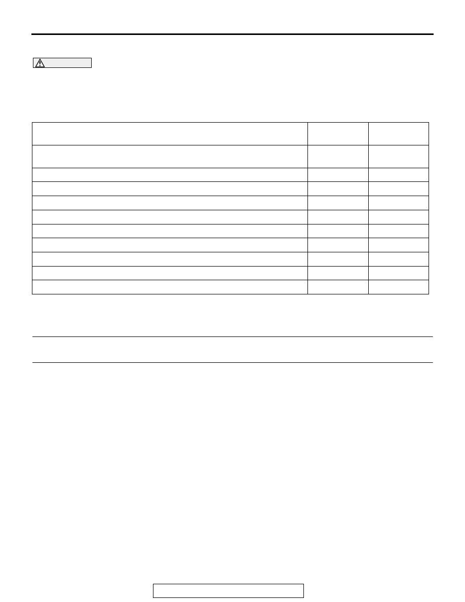
SYMPTOM CHART
M1552009900730
CAUTION
During diagnosis, a DTC code associated with
other system may be set when the ignition switch
is turned on with connector(s) disconnected. On
completion, confirm all systems for DTC code(s).
If DTC code(s) are set, erase them all.
SYMPTOM PROCEDURES
INSPECTION PROCEDURE 1: When the A/C is Operation, Temperature Inside the Passenger
Compartment does not Decrease (Cool Air is not Emitted).
.
TECHNICAL DESCRIPTION (COMMENT)
The blower system or the compressor system may
be defective if there is no cool air coming from the
vents.
.
TROUBLESHOOTING HINTS
• Malfunction of blower motor
• Malfunction of A/C-ECU
• Malfunction of A/C compressor
SYMPTOM
INSPECTION
PROCEDURE
REFERENCE
PAGE
When the A/C is operating, temperature inside the passenger
compartment does not decrease (cool air is not emitted).
1
Malfunction of the A/C-ECU power supply system.
2
The compressor dose not work.
3
Blower fan and motor do not turn.
4
Blower air amount cannot be changed.
5
Outside/Inside air changeover is not possible.
6
A/C outlet air temperature does not increase.
7
Air outlet vent cannot be changed.
8
Rear window defogger function does not operate.
10
Blower motor power supply system.
11