Mitsubishi Outlander GS45X. Manual - part 76


  Index      Mitsubishi     Mitsubishi Outlander GS45X - service repair manual


Search            


Content   ..  74  75  76  77   ..


Mitsubishi Outlander GS45X. Manual - part 76


DOME LIGHT

TSB Revision

CHASSIS ELECTRICAL

54A-301

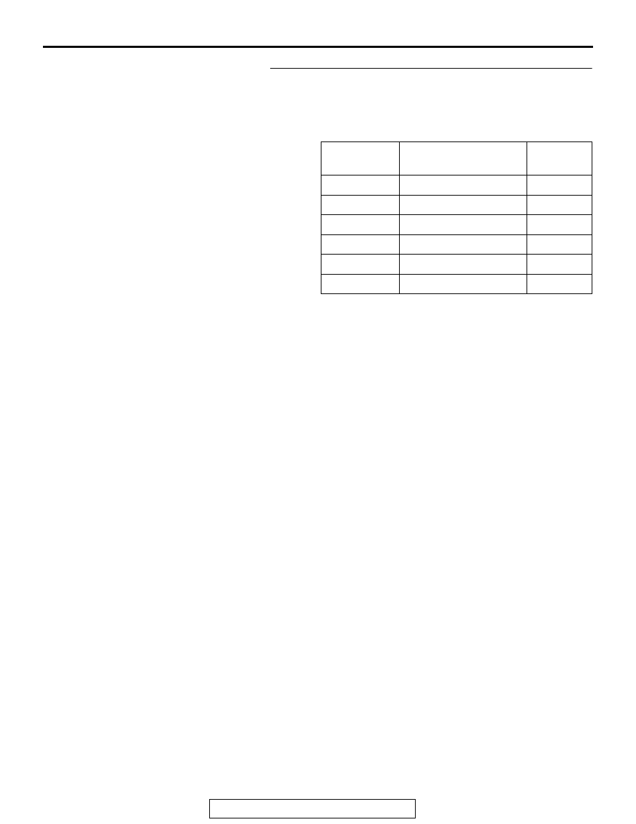
STEP 3. Using scan tool MB991958, check data list.
Use the ETACS-ECU data list to check the signals related to 
the interior light auto-cut function.

• Turn the ignition switch to the "LOCK" (OFF) position.

• Open each door.

Q: Does scan tool MB991958 display the items "IG 

voltage", "ACC switch", "As door ajar switch", "RR door 
ajar switch", and "RL door ajar switch" as normal 
condition?
YES <Normal conditions are displayed for all items.>  : 

Go to Step 4.

NO <Normal condition is not displayed for item No. 
254.>  : 
Troubleshoot the ETACS-ECU. Refer to Inspection 

Procedure 2 "ETACS-ECU does not receive any 
signal from the ignition switch (IG1)" 

P.54A-788

.

NO <Normal condition is not displayed for item No. 
288.>  : 
Troubleshoot the ETACS-ECU. Refer to Inspection 

Procedure 1 "ETACS-ECU does not receive any 
signal from the ignition switch (ACC)" 

P.54A-786

.

NO <Normal condition is not displayed for item No. 
256.>  : 
Troubleshoot the ETACS-ECU. Refer to Inspection 

Procedure 5 "ETACS-ECU does not receive any 
signal from the front door switch (LH)" 

P.54A-801

.

NO <Normal condition is not displayed for item No. 
257.>  : 
Troubleshoot the ETACS-ECU. Refer to Inspection 

Procedure 6 "ETACS-ECU does not receive any 
signal from the front door switch (RH)" 

P.54A-803

.

NO <Normal condition is not displayed for item No. 
258.>  : 
Troubleshoot the ETACS-ECU. Refer to Inspection 

Procedure 7 "ETACS-ECU does not receive any 
signal from the rear door switch (LH)" 

P.54A-805

.

NO <Normal condition is not displayed for item No. 
259.>  : 
Troubleshoot the ETACS-ECU. Refer to Inspection 

Procedure 8 "ETACS-ECU does not receive any 
signal from the rear door switch (RH)" 

P.54A-808

.

Item No.

Item name

Normal 
conditions

Item 254

IG voltage

1 V or less

Item 288

ACC switch

OFF

Item 256

Dr door ajar switch

Open

Item 257

As door ajar switch

Open

Item 258

RR door ajar switch

Open

Item 259

RL door ajar switch

Open

HIGH-MOUNTED STOPLIGHT

TSB Revision

CHASSIS ELECTRICAL

54A-302

STEP 4. Retest the system.
Check that the interior light automatic shutdown function works 
normally.
Q: Is the check result normal?

YES : The trouble can be an intermittent malfunction (Refer 

to GROUP 00 

− How to use 

Troubleshooting/inspection Service Points 

− How to 

Cope with Intermittent Malfunction 

P.00-15

).

NO :  Replace the ETACS-ECU.

ON-VEHICLE SERVICE

CUSTOMIZATION FUNCTION

M1541301200206

With the scan tool MB991958 operation, the follow-
ing functions can be programmed. The programmed 
information is held even when the battery is discon-
nected.

REMOVAL AND INSTALLATION

M1541302700055

Refer to GROUP 52A 

− Headlining 

P.52A-15

.

HIGH-MOUNTED STOPLIGHT

REMOVAL AND INSTALLATION

M1541700200201

Refer to GROUP 51 

− Liftgate spoiler 

P.51-24

.

Adjustment 
item (scan tool 
display)

Adjustment item

Adjustment contents 
(scan tool display)

Adjusting contents

Dome light 
delay timer with 
door

Adjustment of 
interior light delay 
shutdown time

0sec

0 second (no delay shutdown time)

7.5sec

7.5 seconds

15sec

15 seconds

30sec

30 seconds (initial condition)

60sec

60 seconds

120sec

120 seconds

180sec

180 seconds

Interior light 
auto cut timer

Adjustment of 
interior light 
automatic shutdown 
function operation 
time

0min

Without function

3min

3 minutes

30min

30 minutes (initial condition)

60min

60 minutes

LICENSE PLATE LIGHT

TSB Revision

CHASSIS ELECTRICAL

54A-303

LICENSE PLATE LIGHT

REMOVAL AND INSTALLATION

M1541900200238

REMOVAL SERVICE POINT

.

<<A>> LICENSE PLATE LIGHT REMOVAL

Push the license plate light to the left to bend the hook, and 
then remove by disengaging the tab from the liftgate.

AC506864AC

1

2

3

4

Removal Steps 

 <<A>> 

1.

License plate light assembly

2.

Lens

3.

Bulb

4.

Socket

Removal Steps (Continued)

ZC600392

ZC600395

AC703386

Hook

 Section A – A

Liftgate

A

A

Push

Claw

Push

AB

HAZARD WARNING LIGHT SWITCH

TSB Revision

CHASSIS ELECTRICAL

54A-304

HAZARD WARNING LIGHT SWITCH

SPECIAL TOOLS

M1541500100288

Tool

Tool number and 
name

Supersession

Application

MB991958

a. MB991824
b. MB991827
c. MB991910
d. MB991911
e. MB991914
f. MB991825
g. MB991826

M.U.T.-III 
sub-assembly

a. Vehicle 

communication 
interface (V.C.I.)

b. M.U.T.-III USB 

cable

c. M.U.T.-III main 

harness A 
(Vehicles with 
CAN 
communication 
system)

d. M.U.T.-III main 

harness B 
(Vehicles without 
CAN 
communication 
system)

e. M.U.T.-III main 

harness C (for 
Chrysler models 
only)

f. M.U.T.-III 

measurement 
adapter

g. M.U.T.-III trigger 

harness

MB991824-KIT
NOTE: G: 
MB991826 
M.U.T.-III Trigger 
Harness is not 
necessary when 
pushing V.C.I. 
ENTER key.

CAUTION

M.U.T.-III main harness B 
(MB991911) should be used. 
M.U.T.-III main harness A and C 
should not be used for this 
vehicle.
Diagnostic code, service data and 
actuator test check.

MB991910

MB991826

MB991958

MB991911

MB991914

MB991824

MB991827

MB991825

DO NOT USE

a

b

c

d

e

f

g

DO NOT USE


Content   ..  74  75  76  77   ..