Mitsubishi Outlander GS45X. Manual - part 64


  Index      Mitsubishi     Mitsubishi Outlander GS45X - service repair manual


Search            


Content   ..  62  63  64  65   ..


Mitsubishi Outlander GS45X. Manual - part 64


REAR COMBINATION LIGHT

TSB Revision

CHASSIS ELECTRICAL

54A-253

STEP 8. Check ETACS-ECU connectors C-312 for loose, 
corroded or damaged terminals, or terminals pushed back 
in the connector.
Q: Is ETACS-ECU connectors C-312 in good condition?

YES : Go to Step 9.
NO :  Repair the damaged parts.

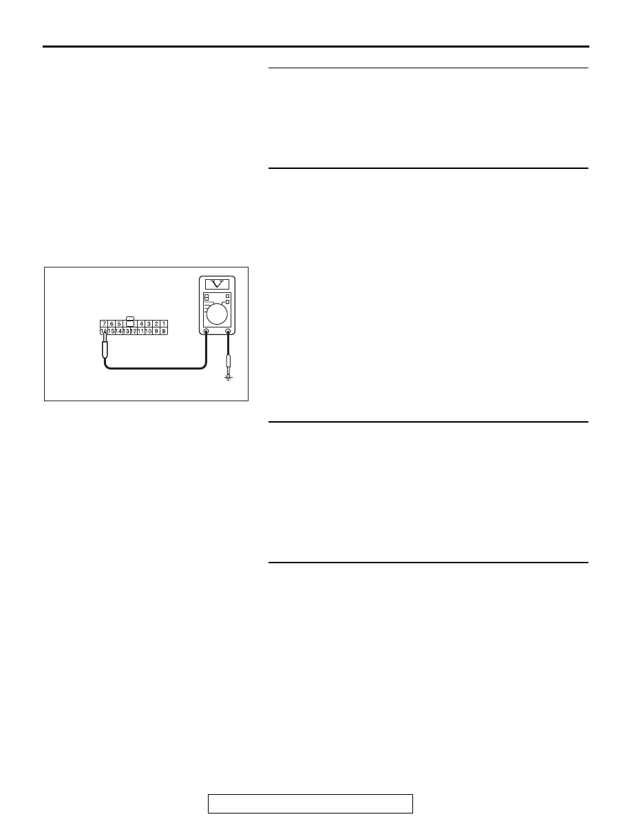
STEP 9. Check the battery power supply circuit to the 
ETACS-ECU. Measure the voltage at ETACS-ECU 
connector C-312.
(1) Disconnect connector measure the voltage available at the 

wiring harness side of the connector.

(2) Disconnecting the ETACS-ECU connector C-312.
(3) Stoplight switch: ON
(4) Measure the voltage between ETACS-ECU connector 

C-312 terminal No. 16 and the body ground.

• The voltage should measure approximately 12 volts 

(battery positive voltage).

Q: Is the measured voltage approximately 12 volts (battery 

positive voltage)?
YES : 
Go to Step 11.
NO :  Go to Step 10.

STEP 10. Check the wiring harness between ETACS-ECU 
connector C-312 (terminal No. 16) and stoplight relay 
connector C-133 (terminal No. 2).

• Check the signal line for short circuit.

Q: Is the wiring harness between ETACS-ECU connector 

C-312 (terminal No. 16) and stoplight relay connector 
C-133 (terminal No. 2) in good condition?
YES : 
Go to Step 11.
NO :  Repair the wiring harness.

STEP 11. Check the wiring harness between stoplight relay 
connector C-133 (terminal No. 4) and intermediate 
connector C-131 (terminal No. 9).
Check the communication line for open or short circuit.
Q: Is the wiring harness between stoplight relay connector 

C-133 (terminal No. 4) and intermediate connector C-131 
(terminal No. 9) in good condition?
YES : 
Go to Step 12.
NO :  Repair the wiring harness.

AC608254EX

 Harness side: C-312

REAR COMBINATION LIGHT

TSB Revision

CHASSIS ELECTRICAL

54A-254

STEP 12. Retest the system
Check that the stoplight illuminates normally.
Q: Does the stoplight relay work normally?

YES : The trouble can be an intermittent malfunction (Refer 

to GROUP 00 

− How to use 

Troubleshooting/inspection Service Points 

− How to 

Cope with Intermittent Malfunction 

P.00-15

).

NO :  Replace the stoplight relay.

REAR COMBINATION LIGHT REMOVAL AND INSTALLATION

M1541402200239

AC703021AB

5

1.2 ± 0.7 N·m
11 ± 6 in-lb

4.5 ± 1.5 N·m
40 ± 3 in-lb

4

2

9

6

3

1

12

11

10

8

7

Removal Steps 

1.

Rear combination light assembly

2.

Rear combination light unit

3.

Socket

4.

Bulb

5.

Grommet

6.

Liftgate cover garnish (Refer to 
GROUP 52A 

− Liftgate Trim 

P.52A-14

)

7.

Taillight assembly

8.

Gasket

9.

Taillight unit

10. Socket
11. Bulb
12. Gasket

Removal Steps (Continued)

FOG LIGHT

TSB Revision

CHASSIS ELECTRICAL

54A-255

FOG LIGHT

SERVICE SPECIFICATIONS

M1540400900187

SPECIAL TOOLS

M1540401800309

Item

Standard value

Limit

Fog light aiming (cutoff line direction) [at 7.62 
m (25.0 ft)]

The horizontal line 153.0 
mm (6.02 inches) (1.15 
degrees angle) below the 
horizontal line (H)

Fog light aiming (vertical direction) [at 7.62 m 
(25.0 ft)]

Area from 53.2 mm (2.09 
inches) (0.4 degrees angle) 
above the cutoff line to 99.8 mm 
(3.93 inches) (0.75 degrees 
angle) below the cutoff line

Fog light aiming (horizontal direction) [at 7.62 
m (25.0 ft)]

Vertical line (V) 

± 599.7 mm (± 

23.6 inches) (

± 4.5 degrees 

angle).

Tool

Tool number and 
name

Supersession

Application

MB990784 
Ornament remover

General service tool

Removal of fog light bezel

MB991223

a. MB991219
b. MB991220
c. MB991221
d. MB991222

Harness set

a. Test harness
b. LED harness
c. LED harness 

adaptor

d. Probe

General service tools Continuity check and voltage 

measurement at harness wire or 
connector

a. Connector pin contact 

pressure inspection

b. Power circuit inspection
c. Power circuit inspection
d. Commercial tester connection

MB990784

MB991223

a

d

c

b

DO NOT USE

BA

FOG LIGHT

TSB Revision

CHASSIS ELECTRICAL

54A-256

DIAGNOSIS

STANDARD FLOW OF DIAGNOSTIC TROUBLESHOOTING

M1540401700153

Refer to GROUP 00 

− Contents of troubleshooting 

P.00-7

.

MB991958

a. MB991824
b. MB991827
c. MB991910
d. MB991911
e. MB991914
f. MB991825
g. MB991826

M.U.T.-III sub 
assembly

a. Vehicle 

communication 
interface (V.C.I.)

b. M.U.T.-III USB 

cable

c. M.U.T.-III main 

harness A 
(Vehicles with 
CAN 
communication 
system)

d. M.U.T.-III main 

harness B 
(Vehicles without 
CAN 
communication 
system)

e. M.U.T.-III main 

harness C (for 
Chrysler models 
only)

f. M.U.T.-III 

measurement 
adapter

g. M.U.T.-III trigger 

harness

MB991824-KIT
NOTE: G: MB991826 
M.U.T.-III Trigger 
Harness is not 
necessary when 
pushing V.C.I. ENTER 
key.

CAUTION

M.U.T.-III main harness B 
(MB991911) should be used. 
M.U.T.-III main harness A and C 
should not be used for this 
vehicle.
Diagnostic code, service data and 
actuator test check.

MB992006
Extra fine probe

Continuity check and voltage 
measurement at harness wire or 
connector.

Tool

Tool number and 
name

Supersession

Application

MB991910

MB991826

MB991958

MB991911

MB991914

MB991824

MB991827

MB991825

DO NOT USE

a

b

c

d

e

f

g

DO NOT USE

MB992006


Content   ..  62  63  64  65   ..