Mitsubishi Outlander GS45X. Manual - part 43


  Index      Mitsubishi     Mitsubishi Outlander GS45X - service repair manual


Search            


Content   ..  41  42  43  44   ..


Mitsubishi Outlander GS45X. Manual - part 43


HEADLIGHT

TSB Revision

CHASSIS ELECTRICAL

54A-169

.

TECHNICAL DESCRIPTION (COMMENT)

When one of the headlights does not illuminate, the 
wiring harness, connector(s), or the bulb may have a 
problem, or the fuse may be burned out.

.

TROUBLESHOOTING HINTS

• Malfunction of the headlight bulbs

• Malfunction of the headlight assembly

• Malfunction of the headlamp control unit

• Damaged harness wires and connectors

DIAGNOSIS

Required Special Tools:

• MB992006: Extra fine probe

• MB991223: Harness set

STEP 1. Check headlight (LOW) connector A-37 <LH>, A-56 
<RH> for loose, corroded or damaged terminals, or 
terminals pushed back in the connector.
Q: Is headlight (LOW) assembly connector A-37 <LH>, A-56 

<RH> in good condition?
YES : 
Go to Step 2.
NO :  Repair the defective connector.

STEP 2. Check bulb.
Check the bulb(s) of headlight that does not illuminate.
NOTE: If discharge-type lower beam headlights do not illumi-
nate, their bulbs cannot be inspected. In this case, assume the 
bulbs to be normal and proceed with steps.
Q: Is the bulb in good condition?

YES : Go to Step 3.
NO :  Replace the bulb(s) of the light that does not 

illuminate.

AC901112

A-56 (B)

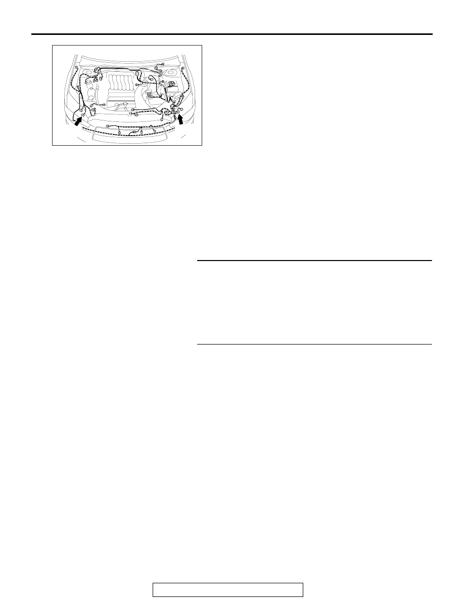
Connectors: A-37, A-56

AR

A-37 (B)

HEADLIGHT

TSB Revision

CHASSIS ELECTRICAL

54A-170

STEP 3. Check the ground circuit to the headlight 
assembly (LOW). Measure the resistance at headlight 
assembly (LOW) connector A-37 <LH>, A-56 <RH>.
(1) Disconnect the connector, and measure at the wiring 

harness side.

(2) Resistance between the connector of light which does not 

illuminate and ground.

Resistance between the A-37 (LH), A-56 (RH) headlight 
assembly connector terminal 6 and ground. <Halogen 
headlight (LOW)>

Resistance between the A-37 (LH), A-56 (RH) headlight 
assembly connector terminal 5 and ground. <Discharge 
headlight (LOW)>

OK: The resistance should be 2 

Ω or less.

Q: Is the measured resistance 2 

Ω or less?

YES : Go to Step 5.
NO :  Go to Step 4.

STEP 4. Check the wiring harness between headlight 
assembly (LOW) connector A-37 <LH>, A-56 <RH> 
(terminal 6 <halogen headlight> or 5 <discharge 
headlight>) and ground.

• Check the ground wires for open circuit.

Q: Is the wiring harness between headlight assembly 

(LOW) connector A-37 <LH>, A-56 <RH> (terminal 6 
<halogen headlight> or 5 <discharge headlight>) and 
ground in good condition?
YES : 
The trouble can be an intermittent malfunction (Refer 

to GROUP 00 - How to Cope with Intermittent 
Malfunction 

P.00-15

).

NO :  The wiring harness may be damaged or the 

connector(s) may have loose, corroded or damaged 
terminals, or terminals pushed back in the connector. 
Repair the wiring harness as necessary. Verify that 
the headlights illuminate normally.

AC702818 DU

Harness side: A-37, A-56

AC702818DV

Harness side: A-37, A-56

HEADLIGHT

TSB Revision

CHASSIS ELECTRICAL

54A-171

STEP 5. Check the wiring harness between headlight 
assembly (LOW) connector A-37 <LH>, A-56 <RH> 
(terminal 1 and 2 <halogen headlight> or 1 and 12 
<discharge headlight>) and headlight relay (LOW) 
connector A-28X or headlight relay (HIGH) connector 
A-20X (terminal 3).

• Check the power supply line for open circuit.

Q: Is the wiring harness between headlight assembly 

(LOW) connector A-37 <LH>, A-56 <RH> (terminal 1 and 
2 <halogen headlight> or 1 and 12 <discharge 
headlight>) and headlight relay (LOW) connector A-28X 
or headlight relay (HIGH) connector A-20X (terminal 3) 
in good condition?
YES : 
Replace the headlight assembly that does not 

illuminate.

NO :  The wiring harness may be damaged or the 

connector(s) may have loose, corroded or damaged 
terminals, or terminals pushed back in the connector. 
Repair the wiring harness as necessary. Verify that 
the headlights illuminate normally.

Inspection Procedure 6: High-beam indicator light does not illuminate normally.

CAUTION

Whenever the ECU is replaced, ensure that the power sup-
ply circuit, the ground circuit and the communication cir-
cuit are normal.

.

TECHNICAL DESCRIPTION (COMMENT)

If the high-beam indicator does not illuminate normally, the har-
ness in the CAN bus lines, connector(s), ETACS-ECU, or com-
bination meter may have a problem.

.

TROUBLESHOOTING HINTS

• Malfunction of the ETACS-ECU

• Malfunction of combination meter

• Damaged harness wires and connectors

DIAGNOSIS

Required Special Tools:

• MB991958 Scan Tool (M.U.T.-III Sub Assembly)

• MB991824: Vehicle Communication Interface (V.C.I.)

• MB991827 M.U.T.-III USB Cable

• MB991910 M.U.T.-III Main Harness A (Vehicles with 

CAN communication system)

HEADLIGHT

TSB Revision

CHASSIS ELECTRICAL

54A-172

STEP 1. Check of headlight (high-beam).
Check that the headlights (high-beam) illuminate/extinguish 
normally when the lighting switch is operated.
Q: Is the check result normal?

YES : Go to Step 2.
NO :  Refer to Inspection Procedure 2 "None of headlights 

(high-beam) illuminates." 

P.54A-159

.

STEP 2. Using scan tool MB991958, diagnose the CAN bus 
line.

CAUTION

To prevent damage to scan tool MB991958, always turn the 
ignition switch to the "LOCK" (OFF) position before con-
necting or disconnecting scan tool MB991958.
(1) Connect scan tool MB991958. Refer to "How to connect the 

Scan Tool (M.U.T.-III) 

P.54A-123

."

(2) Turn the ignition switch from "LOCK" (OFF) position to "ON" 

position.

(3) Diagnose the CAN bus line.
(4) Turn the ignition switch to the "LOCK" (OFF) position.
Q: Is the CAN bus line found to be normal?

YES : Go to Step 3.
NO :  Repair the CAN bus line. (Refer to GROUP 54C, 

Diagnosis 

P.54C-17

).

STEP 3. Using scan tool MB991958, read the ETACS-ECU 
diagnostic trouble code.
(1) Connect scan tool MB991958. Refer to "How to connect 

scan too (M.U.T.-III) 

P.54A-123

."

(2) Turn the ignition switch to the "ON" position.
(3) Check whether the ETACS-ECU related DTC is set.
(4) Turn the ignition switch to the "LOCK" (OFF) position.
Q: Is the DTC set?

YES : Diagnose the ETACS-ECU. Refer to ETACS, 

Diagnosis 

P.54A-732

.

NO :  Go to Step 4.

ZC501967

AC404789

AC702802

MB991824

MB991827

MB991910

Data link

connector

AB


Content   ..  41  42  43  44   ..