Mitsubishi Outlander (2013+). Manual - part 744
TROUBLESHOOTING
HEATER, AIR CONDITIONER AND VENTILATION
55-32
2
ILO-
−
−
−
3
HTR3
4
HTR2
5
HTR1
6
− 11
−
12
AC/P
A/C pressure sensor input
Refer to
Refer to
13
INC
Interior temperature sensor
Sensor probe
temperature: 25
°C (4.0
k
Ω)
2.1 to 2.7 V
14
− 16
−
−
−
−
17
SENG
Sensor earth
Always
1 V or less
18
E
Earth
19
B/UP
Battery power supply
System voltage
20
IG1
IG power supply
Ignition switch: ON
21
P/TC
Power transistor (DRAIN)
Air volume control dial:
Maximum air volume
0 to 2 V
22
ILL+
−
−
−
23
ILO+
24
ILL-
25
P/TB
Power transistor (GATE)
Air volume control dial:
Maximum air volume
System voltage
26
− 30
−
−
−
−
31
CANL
32
CANH
41
IG1
Motor power supply
Ignition switch: ON
System voltage
42
A/PB'
Air mixing damper control motor*
1
or Air mixing damper control
motor (RH)*
2
−
−
43
A/PA'
44
A/PB
45
A/PA
46
A/DB'
Air mixing damper control motor
(LH)*
2
47
A/DA'
48
A/DB
49
A/DA
50
+
Fin thermo sensor
Sensor probe
temperature: 25
°C (4.0
k
Ω)
2.1 to 2.7 V
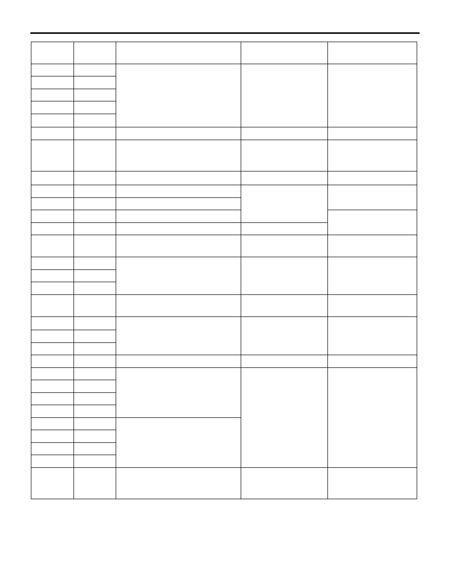
Terminal
No.
Terminal
code
Check item
Check condition
Normal condition