Mitsubishi Outlander (2013+). Manual - part 741


  Index      Mitsubishi     Mitsubishi Outlander - service repair manual 2013 year


Search            


Content   ..  739  740  741  742   ..


Mitsubishi Outlander (2013+). Manual - part 741


TROUBLESHOOTING

HEATER, AIR CONDITIONER AND VENTILATION

55-20

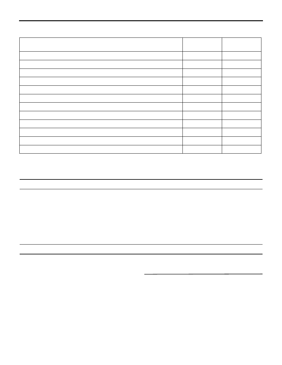
TROUBLE SYMPTOM CHART

M1554005002685

Trouble symptom

Inspection 
procedure No.

Reference 
page

Communication with the M.U.T.-III is not possible

1

P.55-20

Cool air does not come

2

P.55-20

The blower does not work

3

P.55-21

The blower air volume cannot be changed

4

P.55-22

The inside/outside air changeover is impossible

5

P.55-23

The A/C compressor does not work

6

P.55-23

A/C outlet air temperature cannot be set

7

P.55-25

Air outlets changeover is impossible

8

P.55-26

Ambient temperature sensor system

9

P.55-26

A/C pressure sensor system

10

P.55-27

Blower motor power supply system

11

P.55-27

A/C-ECU power supply system

12

P.55-28

SYMPTOM PROCEDURES

INSPECTION PROCEDURE 1: Communication with the M.U.T.-III is not possible.

COMMENTS ON TROUBLE SYMPTOM

If communication with all other systems is not possi-
ble, there is a high possibility that there is a malfunc-
tion of the diagnosis line. If only the A/C system can 
not communicate with the M.U.T.-III, the heater con-
troller assembly (A/C-ECU) may be defective.

PROBABLE CAUSE

Malfunction of the heater controller assembly 
(A/C-ECU)

INSPECTION PROCEDURE 2: Cool air does not come

CIRCUIT OPERATION

If the blower air temperature can not be cool when 
turning A/C switch ON and lowering the preset tem-
perature, inadequate refrigerant quantity, sensors, 
harness or connectors may be suspected.

PROBABLE CAUSE

Damaged wiring harness or connectors

DIAGNOSIS PROCEDURE

STEP 1. Check the blower operation
Check that air blows through the air outlets.
(1) Turn the ignition switch to the ON position.
(2) Blower knob: Other than OFF
(3) Check that the air comes out of the blower.

Q: Is the check result normal?

YES : 

Go to Step 2.

NO : 

Refer to Inspection Procedure 3 "The 
blower does not work 

P.55-21

".

TROUBLESHOOTING

HEATER, AIR CONDITIONER AND VENTILATION

55-21

STEP 2. Check the A/C compressor operation
Check that the compressor operates under the fol-
lowing conditions.

• Engine operation

• Air conditioner switch: ON

• Blower knob: Maximum air volume

• Temperature control dial: 18°C (MAX COOL)

NOTE: The compressor does not work when the 
blower intake temperature is 0

°

C or less.

Q: Is the check result normal?

YES : 

Go to Step 3.

NO : 

Refer to Inspection Procedure 6 "The A/C 
compressor does not work 

P.55-23

",

STEP 3. M.U.T.-III CAN bus diagnostics
Use the M.U.T.-III to diagnose the CAN bus lines.

Q: Is the check result normal?

YES : 

Go to Step 4.

NO : 

Repair the CAN bus lines. (Refer to GROUP 
54C 

− Troubleshooting ).

STEP 4. M.U.T.-III diagnosis code
Check that the diagnosis code related to the air con-
ditioner is not set.

Q: Is the diagnosis code set?

YES : 

Carry out the diagnosis code procedures. 

Refer to 

P.55-7

.

NO : 

Go to Step 5.

STEP 5. Refrigerant level check
Check that the refrigerant level is adequate. Refer to 

P.55-34

.

Q: Is the check result normal?

YES : 

Intermittent malfunction (Refer to GROUP 

00, How to Cope with Intermittent 
Malfunction ).

NO : 

Charge or remove the refrigerant level. 
Refer to 

P.55-34

.

INSPECTION PROCEDURE 3: The blower does not work

COMMENTS ON TROUBLE SYMPTOM

If the blower motor does not operate, the blower 
motor circuit system may be defective.

PROBABLE CAUSES

• Malfunction of the blower motor

• Malfunction of the power transistor

• Malfunction of the heater controller assembly 

(A/C-ECU)

• Damaged wiring harness or connectors

DIAGNOSIS PROCEDURE

STEP 1. M.U.T.-III CAN bus diagnostics
Use the M.U.T.-III to diagnose the CAN bus lines.

Q: Is the check result normal?

YES : 

Go to Step 2.

NO : 

Repair the CAN bus lines (Refer to GROUP 
54C 

− Troubleshooting ).

STEP 2. M.U.T.-III diagnosis code.
Recheck if the diagnosis code is set.
(1) Erase the diagnosis code.
(2) Ignition switch: LOCK (OFF) to ON
(3) Check if the diagnosis code is set.

Q: Is the diagnosis code set?

YES : 

Carry out the diagnosis code procedures. 

Refer to 

P.55-7

NO : 

Go to Step 3.

STEP 3. Check the blower relay.
Refer to 

P.55-41

.

Q: Is the blower relay in good condition?

YES : 

Go to Step 4.

NO : 

Replace the blower relay.

STEP 4. Check the blower motor.
Refer to 

P.55-48

.

Q: Is the check result normal?

YES : 

Go to Step 5.

NO : 

Replace the blower motor.

STEP 5. Voltage measurement at blower motor 
connector.
(1) Disconnect the connector, and measure at the 

wiring harness side.

(2) Turn the ignition switch to the ON position.
(3) Voltage between terminal 1 and body earth.

OK: System voltage

Q: Is the check result normal?

TROUBLESHOOTING

HEATER, AIR CONDITIONER AND VENTILATION

55-22

YES : 

Go to Step 6.

NO : 

INSPECTION PROCEDURE 14: Refer to 
"Blower motor power supply system" 

P.55-27

.

STEP 6. Resistance measurement at the C-109 
power transistor connector.
(1) Disconnect the connector, and measure at the 

wiring harness side.

(2) Continuity between terminal 1 and body earth

OK: Continuity exists (2 

 or less)

Q: Is the check result normal?

YES : 

Go to Step 7.

NO : 

Repair the wiring harness wires between 
power transistor connector terminal No. 1 
and body earth.

STEP 7. Check of open circuit in power transistor 
power supply line between blower motor and 
power transistor connector.

Q: Is the check result normal?

YES : 

Go to Step 8.

NO : 

Repair the connector(s) or wiring harness.

STEP 8. Check of open circuit in P/TB and P/TC 
line between blower motor, power transistor and 
heater controller assembly (A/C-ECU) connector.

Q: Is the check result normal?

YES : 

Go to Step 9.

NO : 

Repair the connector(s) or wiring harness.

STEP 9. Replace the power transistor and 
recheck the trouble symptom
Check that the blower motor operates normally.

Q: Is the check result normal?

YES : 

This diagnosis is complete.

NO : 

Replace the heater controller assembly 
(A/C-ECU).

INSPECTION PROCEDURE 4: The blower air volume cannot be changed

COMMENTS ON TROUBLE SYMPTOM

If air volume cannot be adjusted by using the blower 
control, the A/C control panel, the heater controller 
assembly (A/C-ECU) or the power transistor may be 
faulty.

PROBABLE CAUSES

• Malfunction of the power transistor

• Damaged wiring harness or connectors

• Malfunction of the heater controller assembly 

(A/C-ECU)

DIAGNOSIS PROCEDURE

STEP 1. M.U.T.-III CAN bus diagnostics
Use the M.U.T.-III to diagnose the CAN bus lines.

Q: Is the check result normal?

YES : 

Go to Step 2.

NO : 

Repair the CAN bus lines (Refer to GROUP 
54C, Troubleshooting ).

STEP 2. M.U.T.-III diagnosis code
Check that the diagnosis code related to the air con-
ditioner is not set.

Q: Is the diagnosis code set?

YES : 

Carry out the diagnosis code procedures. 

Refer to 

P.55-7

.

NO : 

Go to Step 3.

STEP 3. Resistance measurement at the power 
transistor connector.
(1) Disconnect the connector, and measure at the 

wiring harness side.

(2) Continuity between terminal 1 and body earth

OK: Continuity exists (2 

 or less)

Q: Is the check result normal?

YES : 

Go to Step 4.

NO : 

Repair the wiring harness wires between 
power transistor connector terminal No. 1 
and body earth.

STEP 4. Check of open circuit in P/TB, P/TC and 
E line between blower motor, power transistor, 
earth J/C(DASH) and heater controller assembly 
(A/C-ECU) connector.

Q: Is the check result normal?

YES : 

Go to Step 5.

NO : 

Repair the connector(s) or wiring harness.

TROUBLESHOOTING

HEATER, AIR CONDITIONER AND VENTILATION

55-23

STEP 5. Replace the power transistor and 
recheck the trouble symptom
Check that the blower motor operates normally.

Q: Is the check result normal?

YES : 

This diagnosis is complete.

NO : 

Replace the heater controller assembly 
(A/C-ECU).

INSPECTION PROCEDURE 5: The Inside/Outside Air Changeover is impossible.

COMMENTS ON TROUBLE SYMPTOM

If the air recirculation cannot be changed by using 
the inside air/outside air changeover switch, the 
inside air/outside air changeover motor system may 
be faulty.

PROBABLE CAUSES

• Malfunction of the outside/inside air selection 

damper control motor

• Damaged wiring harness or connectors

• Malfunction of the heater controller assembly 

(A/C-ECU)

DIAGNOSIS PROCEDURE

STEP 1. Check the operation of the heater control 
panel assembly (A/C-ECU)
Check that the A/C switch, rear window defogger 
switch and air volume control dial can operate.

Q: Is the check result normal?

YES : 

Go to Step 2.

NO : 

INSPECTION PROCEDURE 15: Refer to 
heater control panel assembly (A/C-ECU) 
power supply system 

P.55-28

.

STEP 2. M.U.T.-III diagnosis code
Check that the diagnosis code related to the air con-
ditioner is not set.

Q: Is the diagnosis code set?

YES : 

Carry out the diagnosis code procedures. 

Refer to 

P.55-7

.

NO : 

Go to Step 3.

STEP 3. M.U.T.-III actuator test
Carry out the actuator test. (Refer to 

P.55-31

).

Item No.5: In/out select damper (Select 
"position reset".)

Q: Does the blower motor work normally?

YES : 

This diagnosis is complete.

NO : 

Go to Step 4.

STEP 4. Check of open circuit in F/RA, F/RA’ 
F/RB and F/RB’ line between outside/inside air 
selection damper control motor and heater 
control panel assembly (A/C-ECU) connector.

Q: Is the check result normal?

YES : 

Go to Step 5.

NO : 

Repair the connector(s) or wiring harness.

STEP 5. Replace the air outside/inside air 
circulation switching damper motor, and then 
recheck the trouble symptom.
Check to see that the outside air/inside air circulation 
switching damper motor operates normally.

NOTE: Whenever the motor is replaced, initialise the 
motor position by using the Actuator Test.

Q: Is the check result normal?

YES : 

This diagnosis is complete.

NO : 

Replace the heater control panel assembly 
(A/C-ECU).

INSPECTION PROCEDURE 6: The A/C compressor does not work

COMMENTS ON TROUBLE SYMPTOM

When the A/C compressor does not work, the A/C 
compressor circuit system may be defective.

PROBABLE CAUSES

• Malfunction of the A/C compressor

• Malfunction of the A/C compressor relay

• Damaged harness wires or connectors

• Malfunction of the engine-ECU


Content   ..  739  740  741  742   ..