Mitsubishi Outlander (2013+). Manual - part 737
B991367
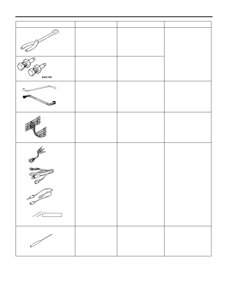
SPECIAL TOOLS
HEATER, AIR CONDITIONER AND VENTILATION
55-4
MB991367
Special spanner
Removal and installation
of the A/C compressor
armature mounting nut
MB991386
Pin
MB990900
MB990900 or
MB991164
Door hinge adjusting
wrench
Removal and installation
of front deck cross
member heater unit
assembly
MB991658
MB991658
Test harness
Inspection of the A/C
pressure sensor
MB991223
a
d
c
b
DO NOT USE
BA
MB991223
a. MB991219
b. MB991220
c. MB991221
d. MB991222
Harness set
a. Test harness
b. LED harness
c. LED harness adapter
d. Probe
Making voltage and
resistance
measurements during
troubleshooting
a. Connect pin contact
pressure inspection
b. Power circuit
inspection
c. Power circuit
inspection
d. Commercial tester
connection
MB992006
MB992006
Extra fine probe
Continuity check and
voltage measurement at
harness wire or
connector
Tool
Number
Name
Use