Mitsubishi Outlander (2013+). Manual - part 720


  Index      Mitsubishi     Mitsubishi Outlander - service repair manual 2013 year


Search            


Content   ..  718  719  720  721   ..


Mitsubishi Outlander (2013+). Manual - part 720


ACC00029

ACC00029

M.U.T.

: Red section on screen

JC

ETACS

KOS

AUDIO

SRS

OSS

ABS/ASC

CVT

ENGINE

EPS

SAS

AWC

MMCS

A/C

ETG

METER

Corner

JC

JC

AR

TROUBLESHOOTING

CONTROLLER AREA NETWORK (CAN)

54C-16

NOTE: 

.

*1

: diagnosis items 2, 3 and 4 should be checked 

AFTER the cause of the fault is determined in 
diagnosis item 1 "Communication with no ECUs 
is possible (CAN-C)". 

*2

: diagnosis items 6, 7 and 8 should be checked 

AFTER the cause of the fault is determined in 
diagnosis item 5 "Communication with no ECUs 
is possible (CAN-C-Mid)". 
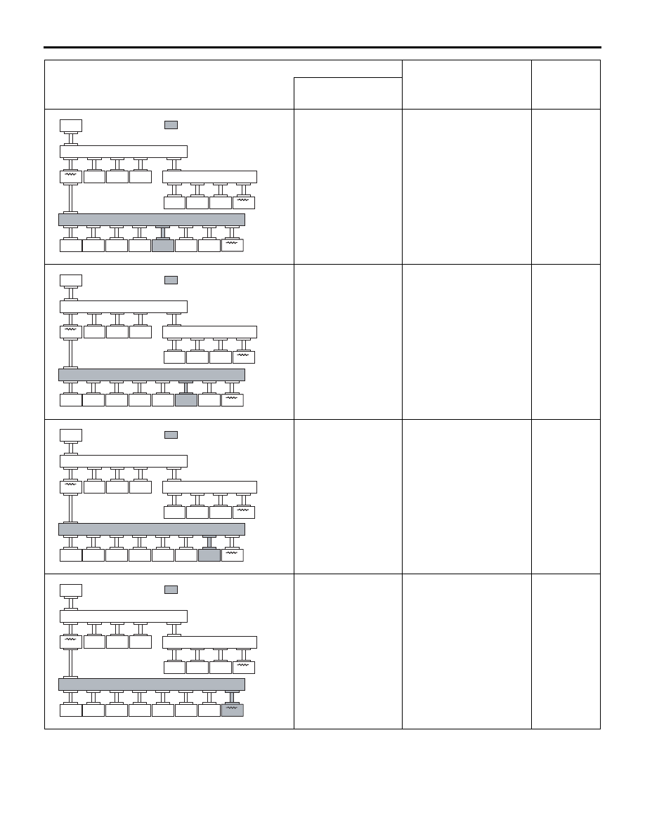
CAN-C-Mid: Failure 
in red displayed 
area is estimated.

Diagnosis Item 22
Diagnose when the 
M.U.T.-III cannot 
receive the data sent by 
corner sensor/back 
sensor-ECU <vehicles 
with reversing sensor 
system>.

P.54C-74

ACC00029

ACC00029

M.U.T.

: Red section on screen

JC

ETACS

KOS

AUDIO

SRS

OSS

ABS/ASC

CVT

ENGINE

EPS

SAS

AWC

MMCS

A/C

ETG

METER

Corner

JC

JC

AS

CAN-C-Mid: Failure 
in red displayed 
area is estimated.

Diagnosis Item 23
Diagnose when the 
M.U.T.-III cannot 
receive the data sent by 
A/C-ECU.

P.54C-75

ACC00029

ACC00029

M.U.T.

: Red section on screen

JC

ETACS

KOS

AUDIO

SRS

OSS

ABS/ASC

CVT

ENGINE

EPS

SAS

AWC

MMCS

A/C

ETG

METER

Corner

JC

JC

AT

CAN-C-Mid: Failure 
in red displayed 
area is estimated.

Diagnosis Item 24
Diagnose when the 
M.U.T.-III cannot 
receive the data sent by 
electric tailgate control 
unit <vehicles with 
electric tailgate>.

P.54C-76

ACC00029

ACC00029

M.U.T.

: Red section on screen

JC

ETACS

KOS

AUDIO

SRS

OSS

ABS/ASC

CVT

ENGINE

EPS

SAS

AWC

MMCS

A/C

ETG

METER

Corner

JC

JC

AU

CAN-C-Mid: Failure 
in red displayed 
area is estimated.

Diagnosis Item 25
Diagnose when the 
M.U.T.-III cannot 
receive the data sent by 
combination meter.

P.54C-77

M.U.T.-III screen

Diagnosis detail

Reference 
page

(The ECUs that are not adopted are not 
displayed.)

Comment

TROUBLESHOOTING

CONTROLLER AREA NETWORK (CAN)

54C-17

CAN-RELATED CONNECTOR POSITION

M1548304101291

Connector 
number

Connector name

A-04

ABS-ECU <Vehicles without ASC>

A-05

ASC-ECU <Vehicles with ASC>

B-07

Engine-ECU

C-04

Corner sensor/back sensor-ECU 
<vehicles with reversing sensor 
system>

C-09

KOS-ECU <vehicles with KOS>

C-23

Instrument panel wiring harness and 
floor wiring harness combination

C-26

Joint connector (CAN-LO)

C-27

Joint connector (CAN-HI)

C-29

Joint connector (CAN1)

C-101

Combination meter

C-109

Radio and CD player <vehicles with 
radio and CD player>

C-113

OSS-ECU <Vehicles with OSS>

C-116

CAN box unit <vehicles with MMCS>

C-123

SRS-ECU

C-126

Instrument panel wiring harness and 
front wiring harness combination

C-131

CVT-ECU

C-205

A/C-ECU

C-218

EPS-ECU

C-220

Diagnosis connector

C-224

4WD-ECU <4WD>

C-309

Steering wheel sensor

C-417

ETACS-ECU

D-10

Electric tailgate control unit <vehicles 
with electric tailgate>

CAN BUS DIAGNOSIS

Diagnosis Item 1: Communication with no ECUs is possible (CAN-C).

CAUTION

When servicing a CAN bus line, earth yourself by 
touching a metal object such as an unpainted 
water pipe. If you fail to do, a component con-
nected to the CAN bus line may be broken.

TROUBLESHOOTING HINTS

• Malfunction in CAN-C (short to earth or power 

supply, wire short to one another)

• Malfunction in the ECUs which are intercon-

nected via CAN-C (internal error)

• Malfunction (open circuit) of wiring harness, con-

nector (s) between the diagnosis connector and 
joint connector(s)

DIAGNOSIS PROCEDURE

STEP 1. Check the CAN-C for short to power 
supply. Voltage measurement at diagnosis 
connector.

CAUTION

A digital multimeter should be used. For details 
refer to 

P.54C-5

.

CAUTION

The test wiring harness should be used. For 
details refer to 

P.54C-5

.

(1) Connect the negative battery terminal, and turn 

the ignition switch to the ON position.

(2) Voltage between diagnosis connector terminal 

No.6 (CAN_H) and body earth

OK: Less than 4.0 V

(3) Voltage between diagnosis connector terminal 

No.14 (CAN_L) and body earth

OK: Less than 4.0 V

Q: Is the check result normal?

Connector 
number

Connector name

TROUBLESHOOTING

CONTROLLER AREA NETWORK (CAN)

54C-18

YES <Voltage is less than 4.0 V in both CAN_H and 
CAN_L> : 

Go to Step 2.

NO <Voltage is 4.0 V or more in either CAN_H or 
CAN_L> : 

Perform diagnosis item 2 "Diagnose 

shorts in the power supply to CAN-C". Refer 
to 

P.54C-18

.

STEP 2. Check the CAN-C for short to earth. 
Resistance measurement at diagnosis 
connector.

CAUTION

A digital multimeter should be used. For details 
refer to 

P.54C-5

.

CAUTION

The test wiring harness should be used. For 
details refer to 

P.54C-5

.

(1) Turn the ignition switch to the LOCK (OFF) 

position.

CAUTION

When measuring the resistance, disconnect the 
negative battery terminal. For details refer to 

P.54C-5

.

(2) Ensure that the negative battery terminal is 

disconnected.

(3) Resistance between diagnosis connector 

terminal No.6 (CAN_H) and body earth

OK: 1 k

 or more

(4) Resistance between diagnosis connector 

terminal No.14 (CAN_L) and body earth

OK: 1 k

 or more

Q: Is the check result normal?

YES <Resistance value is 1 k

 or more in both 

CAN_H and CAN_L> : 

Go to Step 3.

NO <Resistance value is less than 1 k

 in either 

CAN_H or CAN_L> : 

Perform diagnosis item 3 

"Diagnose shorts in the earth to CAN-C". 
Refer to 

P.54C-26

.

STEP 3. Check the CAN-C for short to each other. 
Resistance measurement at diagnosis 
connector.

CAUTION

A digital multimeter should be used. For details 
refer to 

P.54C-5

.

CAUTION

The test wiring harness should be used. For 
details refer to 

P.54C-5

.

(1) Turn the ignition switch to the LOCK (OFF) 

position.

CAUTION

When measuring the resistance, disconnect the 
negative battery terminal. For details refer to 

P.54C-5

.

(2) Ensure that the negative battery terminal is 

disconnected.

(3) Resistance between diagnosis connector 

terminal Nos.6 and 14

OK: 60 

± 10 

Q: Is the check result normal?

YES  : 

The trouble can be an intermittent 

malfunction (Refer to GROUP 00 

− How to 

use Troubleshooting/inspection Service 
Points 

− How to Cope with Intermittent 

Malfunction ).

NO <Resistance value is less than 60 

± 10 > : 

Perform diagnosis Item 4 "Diagnose shorts 
between CAN_H and L lines (CAN-C)". 
Refer to 

P.54C-33

.

NO <Resistance value is 1 k

 or more> : 

Check 

the wires between diagnosis connector and 
joint connector (CAN-HI) for open circuit, 
and check the terminal resistors in the 
engine-ECU and the ETACS-ECU for open 
circuit. Then repair or replace if necessary.

Diagnosis Item 2: Diagnose shorts in the power supply to CAN-C.

CAUTION

• When servicing a CAN bus line, earth yourself 

by touching a metal object such as an 
unpainted water pipe. If you fail to do, a com-
ponent connected to the CAN bus line may be 
broken.

• When the ETACS-ECU of vehicles without 

KOS is replaced, the encrypted code of the 
ignition key needs to be registered to the 
ETACS-ECU. (If the encrypted code is not reg-

istered, the engine cannot be started. Regis-
ter the encrypted code as described in 
GROUP 54A, Immobilizer System 

 How to 

Register Key ID .)

TROUBLE JUDGEMENT CONDITIONS

The M.U.T.-III judges the trouble when it is impossi-
ble to receive the periodically sent data and the volt-
age of CAN_H or CAN_L line is more than 4.0 V.

TROUBLESHOOTING

CONTROLLER AREA NETWORK (CAN)

54C-19

TROUBLESHOOTING HINTS

• Malfunction of the wiring harness

• Malfunction of the connector

• Malfunction of the ETACS-ECU

• Malfunction of the SRS-ECU

• Malfunction of the steering wheel sensor

• Malfunction of the 4WD-ECU <4WD>

• Malfunction of the ABS-ECU <vehicles without 

ASC> or ASC-ECU <vehicles with ASC>

• Malfunction of the EPS-ECU

• Malfunction of the CVT-ECU

• Malfunction of the engine-ECU

DIAGNOSIS PROCEDURE

STEP 1. Check the CAN-C. Voltage measurement 
at diagnosis connector.

CAUTION

A digital multimeter should be used. For details 
refer to 

P.54C-5

.

CAUTION

The test wiring harness should be used. For 
details refer to 

P.54C-5

.

NOTE: This inspection allows you to check that there 
is a short to power supply in either CAN_H line or 
CAN_L line. Thus, in the following steps, check the 
CAN-C that is defective.
(1) Disconnect engine-ECU connector and 

ETACS-ECU connector, and measure the voltage 
at the harness side of diagnosis connector.

(2) Connect the negative battery terminal, and turn 

the ignition switch to the ON position.

(3) Voltage between diagnosis connector terminal 

No.6 (CAN_H) and body earth

OK: 4.0 V or less

(4) Voltage between diagnosis connector terminal 

No.14 (CAN_L) and body earth

OK: 4.0 V or less

(5) Disconnect the negative battery terminal.

Q: Is the check result normal?

YES : 

<Both of the measurement results show 4.0 

V or less> Go to Step 24.

NO : 

<Either of CAN_H line or CAN_L line the 
measurement results show more than 4.0 
V> Go to Step 2.

STEP 2. Check the CAN-C. Voltage measurement 
at C-126 intermediate connector.

CAUTION

A digital multimeter should be used. For details 
refer to 

P.54C-5

.

CAUTION

The test wiring harness should be used. For 
details refer to 

P.54C-5

.

(1) Disconnect the intermediate connector, and 

measure at its female-side intermediate 
connector (at the front wiring harness side).

(2) Connect the negative battery terminal, and turn 

the ignition switch to the ON position.

(3) Voltage between C-126 intermediate connector 

terminal No.15 (CAN_H) and body earth

OK: 4.0 V or less

(4) Voltage between C-126 intermediate connector 

terminal No.16 (CAN_L) and body earth

OK: 4.0 V or less

(5) Disconnect the negative battery terminal.

Q: Is the check result normal?

YES : 

<4.0 V or less> Go to Step 13.

NO : 

<More than 4.0 V> Go to Step 3.

STEP 3. Check the CAN-C between joint 
connector (CAN1) and the engine-ECU. Voltage 
measurement at joint connector (CAN1).

CAUTION

A digital multimeter should be used. For details 
refer to 

P.54C-5

.

CAUTION

The test wiring harness should be used. For 
details refer to 

P.54C-5

.

(1) Disconnect joint connector (CAN1), and measure 

at the wiring harness side.

(2) Connect the negative battery terminal, and turn 

the ignition switch to the ON position.

(3) Voltage between joint connector (CAN1) terminal 

No.10 (CAN_H) and body earth

OK: 4.0 V or less

(4) Voltage between joint connector (CAN1) terminal 

No.21 (CAN_L) and body earth

OK: 4.0 V or less

(5) Disconnect the negative battery terminal.

Q: Is the check result normal?

YES : 

<4.0 V or less> Go to Step 4.

NO : 

<More than 4.0 V> Repair the wiring 
harness between joint connector (CAN1) 
and the engine-ECU connector.


Content   ..  718  719  720  721   ..