Mitsubishi Outlander (2013+). Manual - part 677
REVERSING SENSOR (CORNER SENSOR AND BACK SENSOR)
CHASSIS ELECTRICAL
54A-193
SONAR SWITCH (CORNER SENSOR
SWITCH)
REMOVAL AND INSTALLATION
M1544302300034
Pre-removal Operation
• Instrument Panel Lower Removal (Refer to GROUP 52A
− Instrument Panel Assembly ) <Vehicles without Knee
Air Bag>.
• Instrument Panel Lower LH Removal (Refer to GROUP
52A
− Instrument Panel Assembly ) <Vehicles with Knee
Air Bag>.
Post-installation Operation
• Instrument Panel Lower Installation (Refer to GROUP
52A
− Instrument Panel Assembly ) <Vehicles without
Knee Air Bag>.
• Instrument Panel Lower LH Installation (Refer to GROUP
52A
− Instrument Panel Assembly ) <Vehicles with Knee
Air Bag>.
ACB05547
Sonar switch
AB
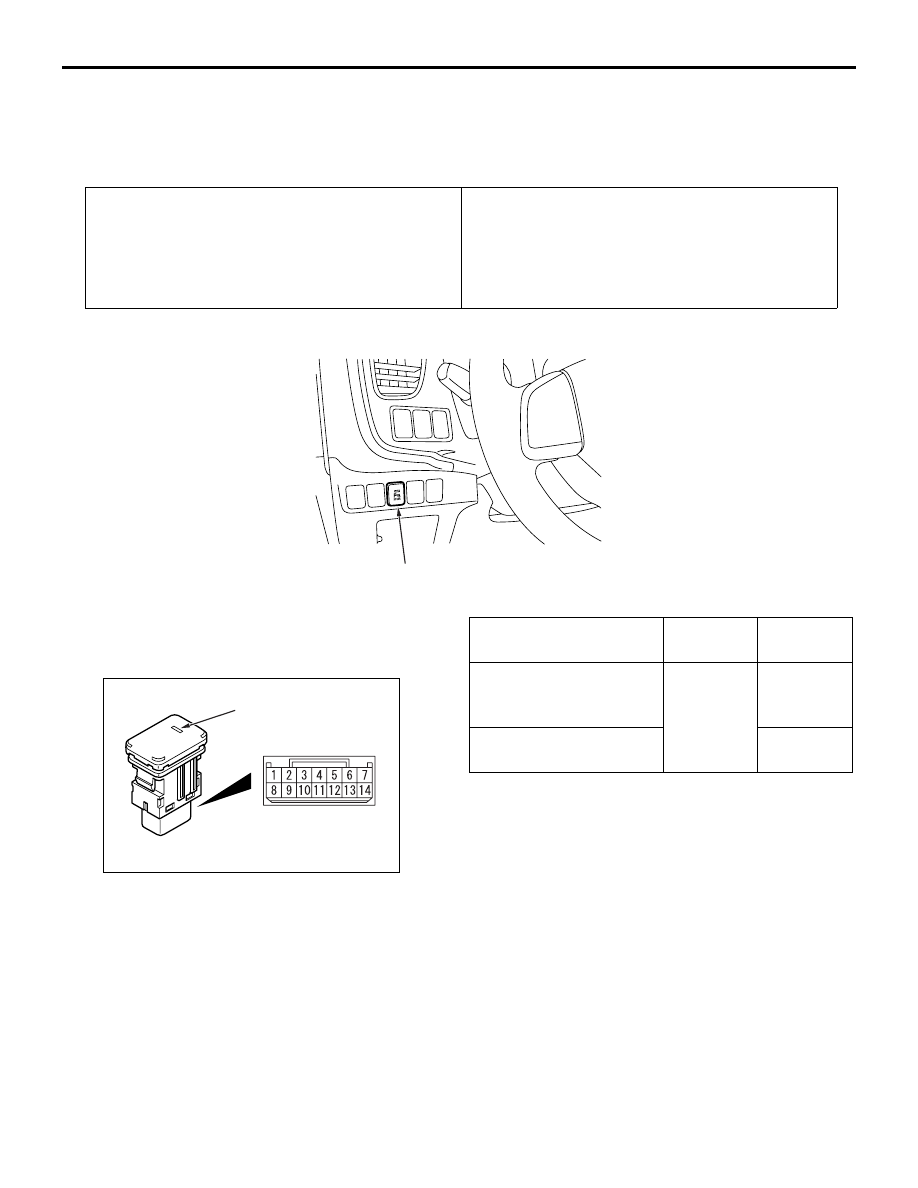
SONAR SWITCH CHECK
M1540701800270
ON/OFF CHECK
ACB05548
AB
Indicator
Switch position
Terminal
number
Normal
condition
ON (switch pushed)
10
− 13
Continuity
exists (2
Ω
or less)
OFF (switch released)
No
continuity
INDICATOR CHECK
Apply the battery voltage to the connector terminal
No. 9, earth the terminal No. 14, and then check that
the indicator illuminates.