Mitsubishi Outlander (2013+). Manual - part 598
TROUBLESHOOTING
SUPPLEMENTAL RESTRAINT SYSTEM (SRS)
52B-43
STEP 6. Check whether the diagnosis code is
reset.
Q: Is the diagnosis code No. B1420 set?
YES :
Replace SRS-ECU (Refer to
NO :
Intermittent malfunction (Refer to GROUP
00
− How to Use
Troubleshooting/Inspection Service Points
−
How to Cope with Intermittent Malfunction ).
Code No.B1421 Right side-airbag module (squib) system (open circuit of squib circuit)
CAUTION
If the diagnosis code B1421 is set to SRS-ECU,
be sure to diagnose the CAN bus line.
OPERATION
In case of side collision, when the impact exceeding
the threshold is applied to the vehicle, and when the
impact is simultaneously detected (turned ON) by the
side impact sensor as well as by the analogue
G-sensor in SRS-ECU, the electric current is sup-
plied from SRS-ECU to the side-airbag module
(squib) of impacted side.
TROUBLE JUDGEMENT
The code is set when the open circuit occurs to the
SRS-ECU side-airbag module (squib) circuit.
PROBABLE CAUSES
• Open circuit to side-airbag module (squib) circuit
• Poor contact of connector
• Malfunction of SRS-ECU
DIAGNOSIS PROCEDURE
STEP 1. M.U.T.-III CAN bus diagnostics.
Use M.U.T.-III to diagnose the CAN bus lines.
Q: Is the check result normal?
YES :
Go to Step 2.
NO :
Repair the CAN bus line (Refer to GROUP
54C
− Troubleshooting ).
STEP 2. Check whether the diagnosis code is
reset.
(1) Connect the negative battery terminal.
(2) After erasing the diagnosis code memory, check
the diagnosis code again.
(3) Disconnect the negative battery terminal.
Q: Is the diagnosis code No. B1421 set?
YES :
Go to Step 3.
NO :
Intermittent malfunction (Refer to GROUP
00
− How to Use
Troubleshooting/Inspection Service Points
−
How to Cope with Intermittent Malfunction ).
STEP 3. Diagnosis check by dummy resistor
connection.
(1) Check that the negative battery terminal is
disconnected. If the negative battery terminal is
connected, disconnect it.
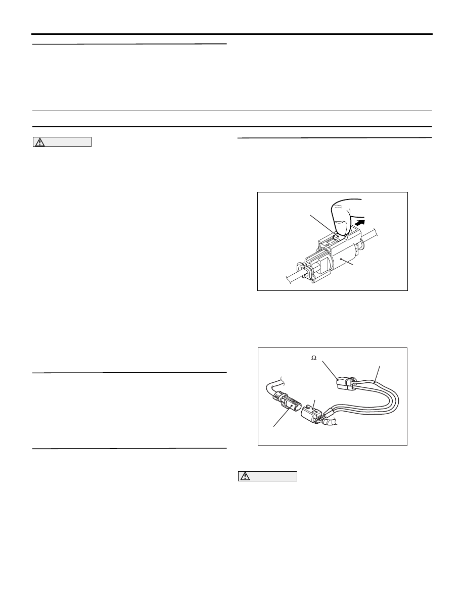
AC706606
AC
Locking button
Side-airbag module
connector
(2) Disconnect the right side-airbag module
connector, unlock the connector by sliding the
locking button to the direction of the arrow as
shown in the figure, and then disconnect the
connector.
AC507310BS
Side-airbag
module (RH) connector
Harness
side connector
MB991865
(Dummy resistor: 3 )
MB991866
(Resistor harness)
(3) Connect special tool dummy resistor (MB991865)
to special tool resistor harness (MB991866).
CAUTION
Do not insert a probe directly into the terminal
from the connector front side as the connector
contact pressure may be weakened.
(4) Insert the resistor harness probe from the back of
right side-airbag module harness side connector.
(5) Connect the negative battery terminal.
(6) After erasing the diagnosis code memory, check
the diagnosis code again.
(7) Disconnect the negative battery terminal.