Mitsubishi Outlander (2013+). Manual - part 40


  Index      Mitsubishi     Mitsubishi Outlander - service repair manual 2013 year


Search            


Content   ..  38  39  40  41   ..


Mitsubishi Outlander (2013+). Manual - part 40


FUEL INJECTION CONTROL

MULTIPOINT FUEL INJECTION (MPI)

13A-28

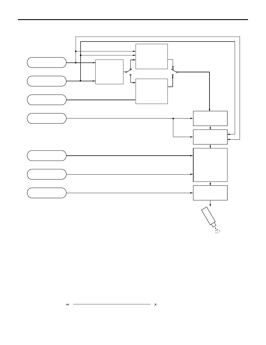
Fuel Injection Volume Control Block Diagram (Normal Operation)

[Injector basic drive time]

Fuel injection is performed once per cycle for each 
cylinder. Basic drive time refers to fuel injection vol-
ume (injector drive time) to achieve theoretical 
air-fuel ratio for the intake air volume of 1 cycle of 1 
cylinder. Fuel injection volume changes according to 

the pressure difference (injected fuel pressure) 
between manifold pressure and fuel pressure (con-
stant). So, injected fuel pressure compensation is 
made to injector drive time for theoretical air-fuel 
ratio to arrive at basic drive time.

AK602278AB

Air flow sensor

Crank angle sensor

Oxygen sensor

Engine coolant
temperature
compensation

Engine coolant
temperature sensor

Manifold absolute
pressure sensor

Fuel pressure
compensation

Barometric pressure
sensor

Battery voltage
compensation

Battery voltage

Basic fuel
injection time
determination

Air fuel ratio
compensation
(Predetermined
compensation)

Oxygen sensor
feedback
compensation

Injector

Acceleration-
deceleration
compensation

AK602279AB

Basic fuel
injection time

Fuel injection pressure compensation

Intake air amount per cycle per cylinder

Theoretical air-fuel ratio

FUEL INJECTION CONTROL

MULTIPOINT FUEL INJECTION (MPI)

13A-29

Intake air volume of each cycle of 1 cylinder is calcu-
lated by engine-ECU based on the airflow sensor 
signal and crank angle sensor signal. Also, during 
engine start, the map value prescribed by the coolant 
temperature sensor signal is used as basic drive 
time.

[Injector drive time compensation]

After calculating the injector basic drive time, the 
engine-ECU makes the following compensations to 
control the optimum fuel injection volume according 
to driving conditions.

List of main compensations for fuel injection control

[Fuel limit control during deceleration]

Engine-ECU limits fuel when decelerating downhill to 
prevent excessive rise of catalytic converter temper-
ature and to improve fuel efficiency.

[Fuel-cut control when over-run]

When engine speed exceeds a prescribed limit 
(6,600 r/min), engine-ECU cuts fuel supply to pre-
vent overrunning and thus protect the engine.

Compensations

Content

Oxygen sensor feedback compensation

The Oxygen sensor signal is used for making the 
compensation to get air-fuel ratio with best cleaning 
efficiency of the 3-way catalytic converter. This 
compensation might not be made sometimes in 
order to improve drivability, depending on driving 
conditions. (Air-fuel ratio compensation is made.) 
The engine-ECU compensates the output signal of 
the oxygen sensor (front) using the output signal of 
the oxygen sensor (rear). This allows the deviation 
of the output signal, caused by the deterioration of 
the oxygen sensor (front), to be solved, then the 
highly accurate exhaust gas control is performed.

Air-fuel ratio compensation

Under driving conditions where oxygen sensor 
feedback compensation is not performed, 
compensation is made based on pre-set map 
values that vary according to engine speed and 
intake air volume.

Engine coolant temperature compensation

Compensation is made according to the engine 
coolant temperature. The lower the engine coolant 
temperature, the greater the fuel injection volume.

Acceleration/ Deceleration compensation

Compensation is made according to change in 
intake air volume. During acceleration, fuel injection 
volume is increased. Also, during deceleration, fuel 
injection volume is decreased.

Fuel injection compensation

Compensation is made according to the pressure 
difference between atmospheric pressure and 
manifold absolute pressure. The greater the 
difference in pressure, the shorter the injector drive 
time.

Battery voltage compensation

Compensation is made depending on battery 
voltage. The lower the battery voltage, the greater 
the injector drive signal time.

Learning value for fuel compensation

Compensation amount is learned to compensate 
feedback of oxygen sensor. This allows system to 
compensate in accordance with engine 
characteristics.

IGNITION TIMING AND CONTROL FOR CURRENT CARRYING TIME

MULTIPOINT FUEL INJECTION (MPI)

13A-30

IGNITION TIMING AND CONTROL FOR CURRENT 

CARRYING TIME

M2132027100573

Ignition timing is pre-set according to engine driving 
conditions. Compensations are made according to 
pre-set values depending on conditions such as 
engine coolant temperature, battery voltage etc. to 
decide optimum ignition timing. Primary current con-
nect/disconnect signal is sent to the power transistor 
to control ignition timing. Ignition is done in sequence 
of cylinders 1, 3, 4, 2.

System Configuration Diagram

1. Ignition power control

Based on the crankshaft position sensor signal and 
camshaft position sensor signal, engine-ECU 
decides the ignition cylinder, calculates the ignition 
timing and sends the ignition coil primary current 
connect/disconnect signal to the power transistor of 
each cylinder in the ignition sequence.

AK502722

1

2

3

4

AN

Engine-
ECU

Air flow sensor

Intake air temperature sensor

Manifold absolute
pressure sensor

Engine coolant
temperature sensor

Inlet camshaft position sensor

Crank angle sensor

Throttle position sensor

Detonation sensor

Ignition switch-ST

Ignition coil

Battery

Spark plug

Cylinder No.

Engine control relay

IGNITION TIMING AND CONTROL FOR CURRENT CARRYING TIME

MULTIPOINT FUEL INJECTION (MPI)

13A-31

2. Spark-advance control and current car-
rying time control

[During start]

Engine-ECU initiates ignition at fixed ignition timing 
(5

° BTDC) synchronized with the crankshaft position 

sensor signal.

[During normal operation]

After determining the basic spark-advance based on 
the intake air volume and engine speed, engine-ECU 
makes compensations based on input from various 
sensors to control the optimum spark-advance and 
current carrying time.

List of main compensations for spark-advance control and current carrying time control

AK604969

Exhaust

AC

Cylinder stroke

No. 1

 Cylinder

No. 3

 Cylinder

No. 4

 Cylinder

No. 2

 Cylinder

Combustion

Intake

Exhaust

Combustion

Compression

Ignition

Intake

Exhaust

Compression

Combustion

Intake

Compression

Intake

Exhaust

Combustion

Compression

H

L

H

L

Crank angle
sensor signal

Inlet camshaft
position sensor
signal

<No. 2 TDC>

<No.1  TDC>

<No. 3 TDC>

<No. 4 TDC>

<No. 2 TDC>

Compensations

Content

Intake air temperature compensation

Compensation is made according to intake air 
temperature. The higher the intake air temperature 
the greater the delay in ignition timing.

Engine coolant temperature compensation

Compensation is made according to engine coolant 
temperature. The lower the engine coolant 
temperature the greater the advance in ignition 
timing.

Knocking compensation

Compensation is made according to generation of 
knocking. The greater the knocking the greater the 
delay in ignition timing.

Stable idle compensation

Compensation is made according to change in idle 
speed. In case engine speed becomes lower than 
target speed, ignition timing is advanced.

Delay compensation when changing shift

During change of shift, sparking is delayed 
compared to normal ignition timing to reduce 
engine output torque and absorb the shock of the 
shift change.


Content   ..  38  39  40  41   ..