Mitsubishi Outlander (2013+). Manual - part 34
GENERAL INFORMATION
MULTIPOINT FUEL INJECTION (MPI)
13A-4
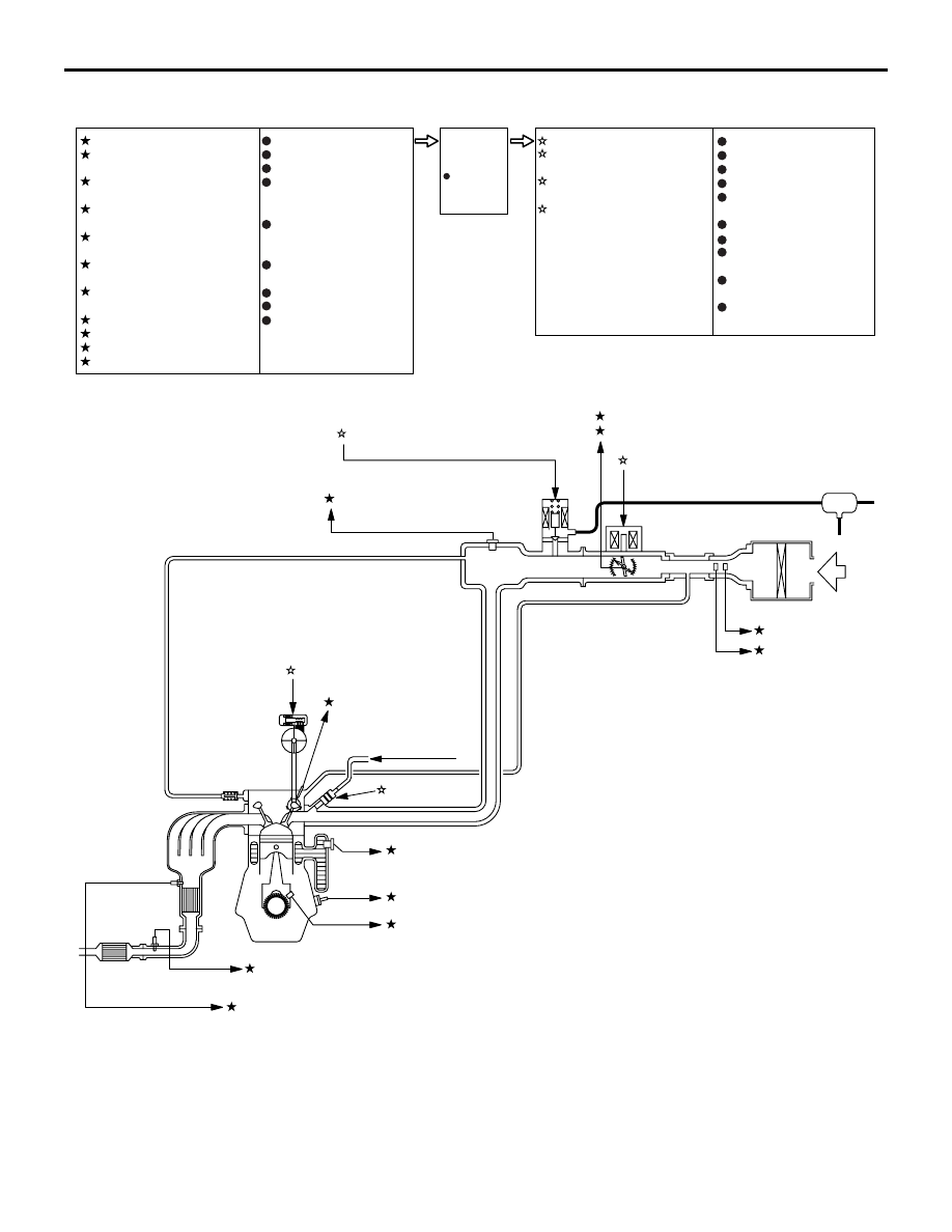
Control System Diagram
AKB00748AB
Air flow sensor
Intake air temperature
sensor
Throttle position sensor
(main)
Throttle position sensor
(sub)
Manifold absolute
pressure sensor
Inlet camshaft position
sensor
Engine coolant
temperature sensor
Detonation sensor
Crank angle sensor
Oxygen sensor (front)
Oxygen sensor (rear)
1
2
3
4
5
6
7
8
9
10
11
Injector
Inlet oil feeder
control valve
Throttle valve control
servo
Purge control solenoid
valve
1
2
3
4
Power supply
Ignition switch-IG
Ignition switch-ST
Accelerator pedal
position
sensor (main)
Accelerator pedal
position
sensor (sub)
Engine oil pressure
switch
Alternator FR terminal
Alternator L terminal
CAN communication
(input signal)
Engine-
ECU
Ignition coil
Engine control relay
Fuel pump relay
Starter relay
Throttle valve control
servo relay
A/C compressor relay
Alternator G terminal
Oxygen sensor (front)
heater
Oxygen sensor (rear)
heater
CAN communication
(input signal)
4 Throttle position sensor (sub)
3 Throttle valve control servo
4 Purge control solenoid valve
2 Inlet oil feeder control valve
1 Injector
Canister
Air
3 Throttle position sensor (main)
5 Manifold absolute pressure
sensor
7 Engine coolant
temperature sensor
8 Detonation sensor
9 Crank angle sensor
10 Oxygen sensor (front)
11 Oxygen sensor (rear)
6 Inlet camshaft
position sensor
From fuel pump
1 Air flow sensor
2 Intake air
temperature
sensor
Catalytic
converter
Barometric
pressure
sensor
Catalytic
converter