Mitsubishi Outlander (2013+). Manual - part 31


  Index      Mitsubishi     Mitsubishi Outlander - service repair manual 2013 year


Search            


Content   ..  29  30  31  32   ..


Mitsubishi Outlander (2013+). Manual - part 31


BASE ENGINE

ENGINE MECHANICAL

11-7

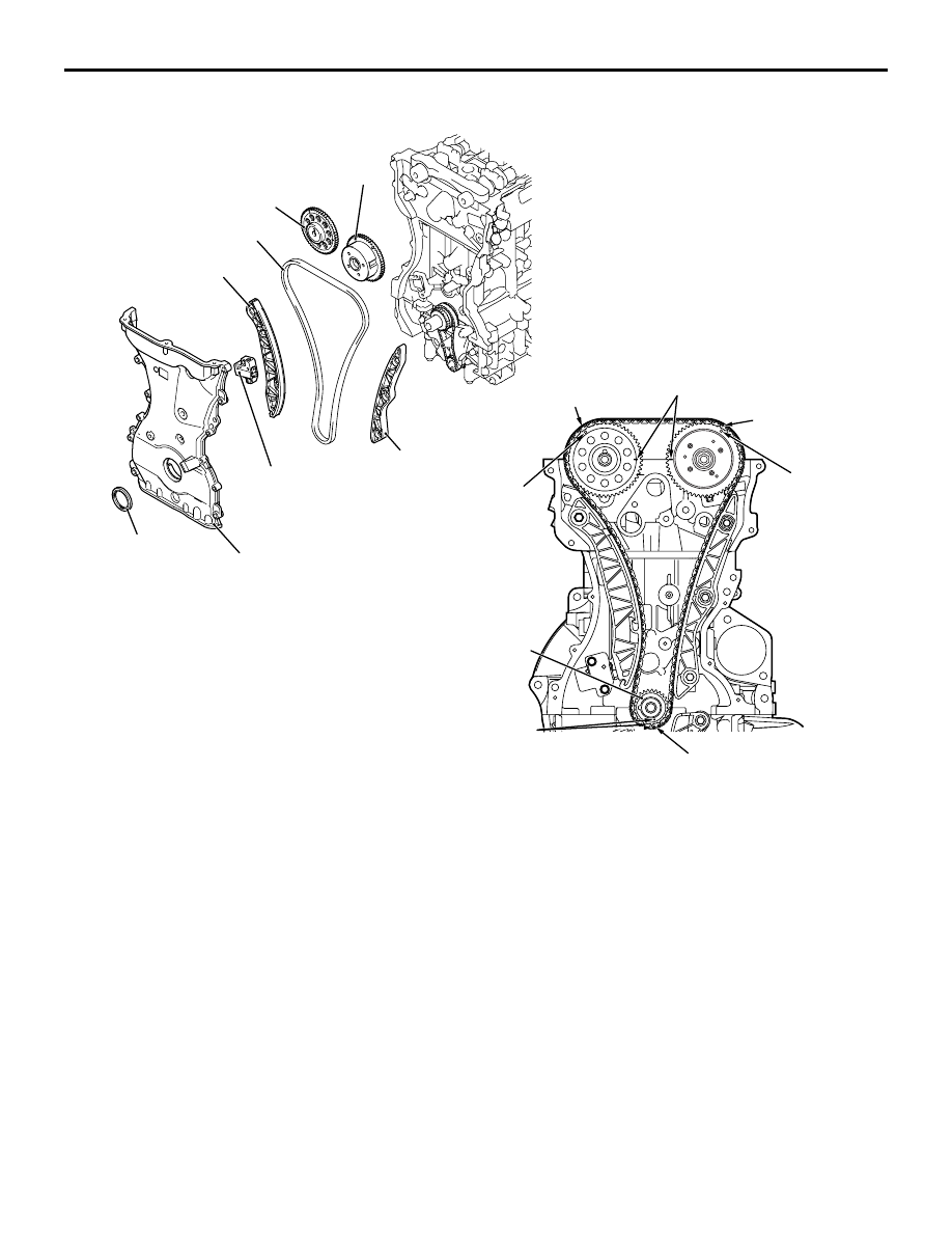
TIMING CHAIN RELATION

1. OIL SEAL

• A front crankshaft oil seal is press-fit into the 

case.

2. TIMING CHAIN CASE

• The engine support bracket, the oil pump and the 

relief valve are integrated as well as water cham-
ber of the water pump.

3. TIMING CHAIN

• The two camshafts are driven by the timing chain 

via the respective sprockets. The timing chain, 
consisting of 180 links, is an endless chain, con-
necting the crankshaft sprocket with the camshaft 
and V.V.T. sprockets. The timing chain is 
equipped with three mark link plates (blue) to cor-
rectly time the two sprockets with each other. The 
timing chain is tensioned by the timing chain ten-
sioner, which has a built-in plunger with plunger 
springs.

4. TIMING CHAIN TENSIONER

• The plunger in the timing chain tensioner directly 

pushes the tension lever, and the pressure auto-
matically adjusts the timing chain tension. A cam 
is provided to lock the plunger in place after the 
engine stops. This helps prevent the timing chain 
from wobbling just after the engine starts. With 
the timing chain tensioner installed, do not crank 
the engine in the reverse direction. This will force 
the plunger to overcome the cam, or even cause 
other problems.

5. TENSIOR LEVER ASSEMBLY

6. CHAIN GUIDE ASSEMBLY

7. CAMSHAFT SPROCKET EXHAUST

8. V.V.T. CAMSHAFT SPROCKET

AKB00853

Inlet V.V.T. sprocket

Exhaust camshaft sprocket

Chain guide

Tensioner lever 
assembly

Crankshaft sprocket

Timing mark

Timing chain
case

Timing chain mark
link plate (blue)

V.V.T. sprocket
timing mark

Timing chain mark
link plate (blue)

Camshaft sprocket
timing mark

Timing chain mark
link plate (blue)

Timing mark

Timing chain

Timing chain
tensioner

Oil seal

AB

BASE ENGINE

ENGINE MECHANICAL

11-8

VALVE RELATION

The valve mechanism is based on a 4-valve DOHC 
(Double Over Head Camshaft) design having the 
camshaft on the upper valve. Each cylinder has two 
intake valves and two exhaust valves, arranged in a 
V-shape pattern.
Camshaft rotation is transmitted via valve tappets to 
the respective valves which open and close accord-
ingly.
1. CAMSHAFT

2. VALVE TAPPET

• Valve tappets are available in 47 thicknesses, at 

0.015 mm intervals between 3.000 mm and 3.690 
mm, to ensure correct valve clearance.

3. VALVE

• The valves have heat-resistance. The entire 

valve surface is treated with nitriding.

4. VALVE STEM SEAL

• The valve stem seals are integrated with the 

valve spring seats.

• The valve stem seal portion excels in sealing per-

formance and is equipped with a spring to pre-
vent oil from descending.

5. VALVE SPRING

• The valve spring has a dual pitch spring to pre-

vent surging in the high speed range.

AK502499

Exhaust camshaft

Inlet camshaft

Valve tappet

Inlet valve

Exhaust valve

AJ

Valve stem seal

Valve spring

BASE ENGINE

ENGINE MECHANICAL

11-9

MIVEC (MITSUBISHI INNOVATIVE VALVE TIMING ELECTRONIC CONTROL SYSTEM) 
RELATION

MIVEC (Mitsubishi Innovative Valve timing Electronic 
Control system) consists of the components illus-
trated above.

The intake valve timing is optimally controlled (con-
tinuously variable) under the changing driving condi-
tions to improve performance in the entire speed 
range.

V.V.T. SPROCKET (VARIABLE VALVE TIMING SPROCKET)

Oil from the oil feeder control valve is sent to the 
V.V.T. sprocket, moving the vane rotor and thus regu-
lating the valve timing.

AKB00854AB

Section A-A

Oil feeder control
valve filter

V.V.T. camshaft
sprocket (Inlet )

Cylinder head

Cylinder block

A

A

Oil feeder
control valve

AKB00855

Timing mark

Valve housing

Sprocket

Retard oil chamber

Valve rotor

Advance oil
chamber

Stopper pin

V.V.T. sprocket
bolt

Vance bushing

Inlet V.V.T. sprocket

AB

BASE ENGINE

ENGINE MECHANICAL

11-10

CAMSHAFT

The lightweight camshaft is achieved by the hollow 
design.
Oil channels run through the intake camshaft, 
through which oil is sent from the oil feeder control 
valve to the V.V.T. sprocket.

A cam position sensing ring is press-fitted onto the 
rear portion of the intake camshaft.

OIL FEEDER CONTROL VALVE (OCV)

The oil feeder control valve is essentially a solenoid 
valve, regulated by the engine-ECU signals to feed 
oil to the V.V.T. sprocket assembly to move the vane 
rotor.

AK502506

Inlet camshaft

Exhaust camshaft

Retard
oil channel

Advance
oil channel

Dowel pin

Hollow section

Sealing cap

Cam position
sensing cam

AH

AKB00856

AB

Spring guide

Valve sleeve

Spool

O-ring

Insulation collar

Stator

Guide cap

Bracket

Yoke

Plunger

Shaft

Terminal

Bobbin

Enamelled copper wire

Drain

Drain

Pump

Pressure
chamber

Default
pressure
chamber


Content   ..  29  30  31  32   ..