Mitsubishi Outlander (2003+). Manual - part 563


  Index      Mitsubishi     Mitsubishi Outlander - service repair manual 2003 year


Search            


Content   ..  561  562  563  564   ..


Mitsubishi Outlander (2003+). Manual - part 563


TROUBLESHOOTING

AUTOMATIC AIR CONDITIONER

55B-67

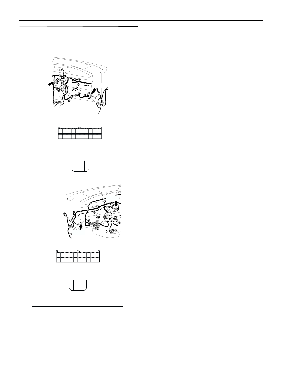
Step 19. Check the wiring harness between C-27 
A/C-ECU connector terminal No.2 and C-32 
blower linear controller connector terminal No.5.

Check the communication line for open or short 
circuit.

Q: Is the check result normal?

YES : 

Replace the air conditioner control panel 

(A/C-ECU) or the blower motor (blower 
linear controller).

NO : 

Repair the wiring harness.

AC301398

Connectors: C-27, C-32 <LHD>

C-32

BP

C-32

Harness side

C-27

C-27(B)

4

6 5

3

2

1

8

2

10 9

1

5

3

4

6

7

20191817161514131211

Harness side

AC308736

Connectors: C-27, C-32 <RHD>

AO

C-32

Harness side

Harness side

C-27

C-32

C-27(B)

4

6 5

3

2

1

8

2

10 9

1

5

3

4

6

7

20191817161514131211

TROUBLESHOOTING

AUTOMATIC AIR CONDITIONER

55B-68

INSPECTION PROCEDURE 5: The blower air volume cannot be changed.

COMMENTS ON TROUBLE SYMPTOM
If the blower air volume can not be changed when 
the blower switch is operated, the circuit between 
blower motor and A/C-ECU may be defective.

Possible causes

Blower motor (blower linear controller)

Damaged the wiring harness or connectors

Malfunction of the automatic air conditioner 
control panel (A/C-ECU)

Step 1. MUT-II/III actuator test

Carry out the actuator test.

Item 01, 02, 03, 04: Blower motor

Q: Does the blower motor work normally? 

YES : 

Replace the automatic air conditioner 

control panel (A/C-ECU)

NO : 

Go to Step 2.

BLOWER
RELAY

BLOWER
LINEAR
CONTROLLER

A/C-ECU

Wire colour code
B : Black     LG : Light green     G : Green     L : Blue      
W : White     Y : Yellow     SB : Sky blue     BR : Brown 
O : Orange     GR : Gray     R : Red     P : Pink     V : Violet        

Blower Motor Circuit

TROUBLESHOOTING

AUTOMATIC AIR CONDITIONER

55B-69

Step 2. Connector check: C-27 A/C-ECU 
connector and C-32 blower linear controller 
connector

Q: Is the check result normal?

YES : 

Go to Step 3.

NO : 

Repair the connector.

Step 3. Check the wiring harness between C-27 
A/C-ECU connector terminal No.2 and C-32 
blower linear controller connector terminal No.5.

Check the communication line for open or short 
circuit.

Q: Is the check result normal?

YES : 

Replace the automatic air conditioner 

control panel (A/C-ECU) or the blower 
motor (blower linear controller).

NO : 

Repair the wiring harness.

AC301398

Connectors: C-27, C-32 <LHD>

C-32

BP

C-32

Harness side

C-27

C-27(B)

4

6 5

3

2

1

8

2

10 9

1

5

3

4

6

7

20191817161514131211

Harness side

AC308736

Connectors: C-27, C-32 <RHD>

AO

C-32

Harness side

Harness side

C-27

C-32

C-27(B)

4

6 5

3

2

1

8

2

10 9

1

5

3

4

6

7

20191817161514131211

TROUBLESHOOTING

AUTOMATIC AIR CONDITIONER

55B-70

INSPECTION PROCEDURE 6: When sunlight intensity changes, blower air temperature does not 
Change.

CIRCUIT OPERATION
When the blower air temperature can not be 
changed even if the preset temperature is changed, 
the sensors may be defective.

TROUBLESHOOTING HINTS

Malfunction of the photo sensor

Damaged the wiring harness or connectors

Malfunction of the A/C-ECU

DIAGNOSIS

STEP 1. Check the defogger and outside/inside 
air selection damper control motor operation.

Q: Do the defogger and outside/inside air selection 

damper control motor work normally?

YES : 

Go to Step 2.

NO : 

Refer to Inspection procedure 10 
"Malfunction of the A/C-ECU power supply 
system 

P.55B-88

."

Step 2. Use the MUT-II/III to confirm a diagnosis 
code.

On completion, check that the diagnosis code is not 
reset.

Q: Is the check result normal?

YES : 

Go to Step 3.

NO : 

Carry the diagnosis code procedures. Refer 
to 

P.55B-4

.

Step 3. Check the MUT-II/III data list.

Item 25: Photo sensor

OK: Check that the volume of insolation 
takes inverse proportion with the MUT-II/III 
displayed voltage.

Q: Is the check result normal?

YES : 

Replace the automatic air conditioner 

control panel (A/C-ECU).

NO : 

Go to Step 4.

Wire colour code
B : Black     LG : Light green     G : Green     L : Blue     W : White     Y : Yellow     SB : Sky blue
BR : Brown     O : Orange     GR : Gray     R : Red     P : Pink     V : Violet   

A/C-ECU

PHOTO SENSOR

Photo Sensor Circuit


Content   ..  561  562  563  564   ..