Mitsubishi Outlander (2003+). Manual - part 458
SYMPTOM PROCEDURES
SMART WIRING SYSTEM (SWS) NOT USING SWS MONITOR
54B-121
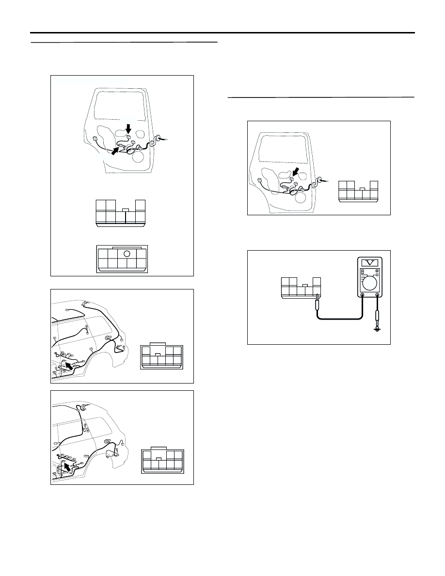
Step 23. Check the wiring harness from E-01
power window sub switch (rear LH) connector
terminal No.1 to body earth.
NOTE:
Prior to the wiring harness inspection, check
intermediate connectors E-09 and D-26, and repair if
necessary.
•
Check the earth wires for open circuit.
Q: Is the check result normal?
YES :
The trouble can be an intermittent
malfunction (Refer to GROUP 00, How to
Cope with Intermittent Malfunction
NO :
Repair the wiring harness.
Step 24. Measure the voltage at E-01 power
window sub switch (rear LH) connector.
(1) Disconnect the connector, and measure at the
wiring harness side.
(2) Turn the ignition switch to the ON position.
(3) Voltage between terminal 4 and body earth
OK: System voltage
Q: Is the check result normal?
YES :
Go to Step 27.
NO :
Go to Step 25.
AC308790
Connectors: E-01, E-09
AB
E-01
Harness side
E-09
E-01
E-09
1
4
5
3 2
7 6
8
4
1
5
2
7
6
8
3
AC308783
Connector: D-26 <LHD>
AB
8
3
1
4 5 6
2
7
AC308787
Connector: D-26 <RHD>
AB
8
3
1
4 5 6
2
7
AC308789
Connector: E-01
AC
Harness side
1
4
5
3 2
7 6
8
1
4
5
3 2
7 6
8
AC301462
Connector E-01
(Harness side)
AB