Mitsubishi Outlander (2003+). Manual - part 450
SYMPTOM PROCEDURES
SMART WIRING SYSTEM (SWS) NOT USING SWS MONITOR
54B-89
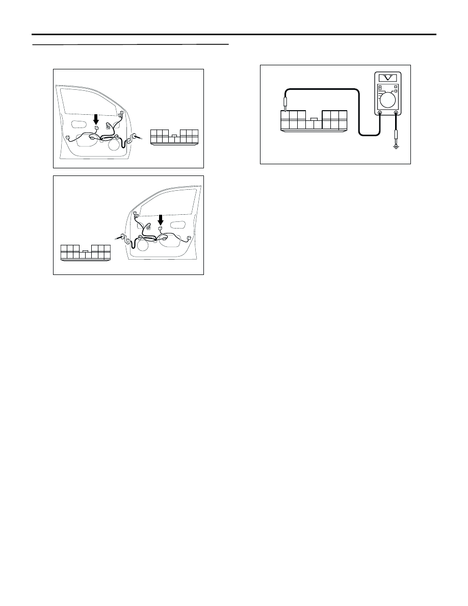
Step 5. Measure the voltage at the E-05 power
window main switch connector.
(1) Disconnect the connector, and measure at the
wiring harness side.
(2) Turn the ignition switch to the ON position.
(3) Voltage between terminal 6 and body earth
OK: System voltage
Q: Is the check result normal?
YES :
Go to Step 9.
NO :
Go to Step 6.
AC308791
10
1
6
14
5
12
13
4
11
7
2
3
8
9
AC
Connector: E-05
Harness side
<LHD>
AC308797
10
1
6
14
5
12
13
4
11
7
2
3
8
9
AC
Connector: E-05
Harness side
<RHD>
10
1
6
14
5
12
13
4
11
7
2
3
8
9
AC301469
Connector E-05
(Harness side)
AB