Mitsubishi Outlander (2003+). Manual - part 239


  Index      Mitsubishi     Mitsubishi Outlander - service repair manual 2003 year


Search            


Content   ..  237  238  239  240   ..


Mitsubishi Outlander (2003+). Manual - part 239


DIFFERENTIAL CARRIER ASSEMBLY

REAR AXLE <4WD>

27B-27

Use the following special tools to press-fit the drive 
pinion rear bearing outer race.

Installer bar (MB990938)

Installer adapter (MB990935)

>>C<< DRIVE PINION FRONT BEARING OUTER 
RACE PRESS-FITTING

Use the following special tools to press-fit the drive 
pinion front bearing outer race.

Installer bar (MB990938)

Installer adapter (MB990932)

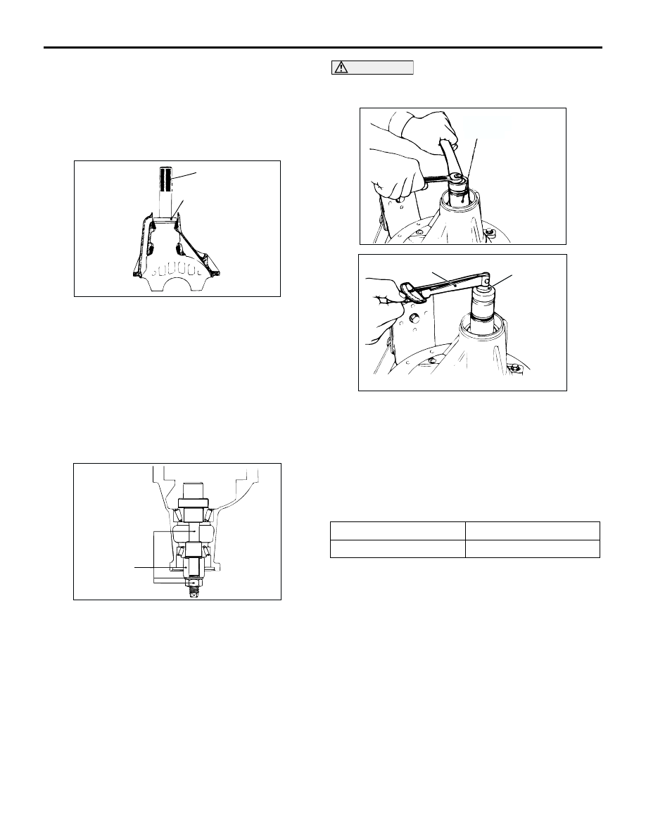
>>D<< DRIVE PINION HEIGHT ADJUSTMENT
Adjust the drive pinion height by the following 
procedures:
1. Apply multipurpose grease to the washer of 

special tool drive pinion gauge asseembly 
(MB990836).

2. Install special tool, drive pinion front and rear 

bearing inner races to the differential carrier as 
shown in the illustration.

CAUTION

There should be no gear oil adhered to the 
bearing.

3. Tighten the nut of special tool a little at a time, 

while measuring the turning torque of the drive 
pinion by using the following special tools. Then 
confirm that the turning torque (without the drive 
pinion oil seal) is at the standard value.

Preload socket (MB990326)

Torque wrench (MB990685)

Standard value:

NOTE: Because the special tool preload socket 
(MB990326) cannot be turned one turn, turn it 
several times within the range that it can be 
turned; then, after fitting to the bearing, measure 
the turning torque.

4. Clean the side bearing seat of the differential 

carrier and bearing caps.

AC102908

MB990938

MB990932

AD

AC102909

MB990836

AC

Bearing division

Turning torque

New

0.9 

 1.2 N

m

AC102910 AD

MB990836

AC102911

MB990326

AC

MB990685

DIFFERENTIAL CARRIER ASSEMBLY

REAR AXLE <4WD>

27B-28

5. Place the following special tools in the side 

bearing seat of the differential carrier, and position 
the notch as shown in the illustration. Then install 
the bearing caps.

Cylinder gauge (MB990392)

Drive pinion gauge assembly (MB990836)

6. Use a thickness gauge to measure the clearance 

(A) between special tools.

7. Remove the bearing caps and special tools.

8. Use a micrometer to measure the shown 

dimensions (B, C) of special tools.

9. Install the bearing cap, and then use a cylinder 

gauge to measure the inside diameter (D) of the 
bearing cap.

10.Calculate thickness (F) of the required drive 

pinion rear shim by the following formula. Select a 
shim which most closely matches this thickness.
F = A + B + C 

 1/2D 

 86.00 mm

11.Fit the selected drive pinion rear shim(s) to the 

drive pinion, and press-fit the drive pinion rear 
bearing inner race by using special tool bearing 
installer (MB990728).

>>E<< DRIVE PINION TURNING TORQUE 
ADJUSTMENT/OIL SEAL INSTALLATION
Adjust the drive pinion turning torque by the following 
procedures:
1. Insert the drive pinion into the differential carrier, 

and then install the following parts in sequence 
from the carrier rear side: drive pinion spacer, 
drive pinion front shim , drive pinion front bearing 
inner race and companion flange.
NOTE: Do not install the oil seal.

2. Tighten the companion flange self-locking nut to 

the specified torque while holding the companion 
flange with special tool end yoke holder 
(MB990850).

Tightening torque: 186 

±

 29 N

m

AC102912

MB990836

A

AD

Notch

Thickness
gauge

MB990392

AC102913

C

B

AC

AC102914

Cylinder gauge

AC

D

ACX02432

MB990728

MB990728

MB990728

AD

Drive pinion
rear shim

AC201179 AB

MB990850

DIFFERENTIAL CARRIER ASSEMBLY

REAR AXLE <4WD>

27B-29

CAUTION

There should be no gear oil adhered to the 
bearing.

3. Use the following special tools MB990685 and 

MB990326 to measure the drive pinion turning 
torque (without the drive pinion oil seal).

Preload socket (MB990326)

Torque wrench (MB990685)

Standard value:

4. If the drive pinion turning torque is not within the 

standard value, adjust the turning torque by 
replacing the drive pinion front shim(s) or the drive 
pinion spacer.
NOTE: 

When selecting the drive pinion front shims, if the 
number of shims is large, reduce the number of 
shims to a minimum by selecting the drive pinion 
spacers.
Select the drive pinion spacer from the following 
two types.

5. Remove the companion flange and drive pinion 

again. Then insert the drive pinion front bearing 
inner race into the differential carrier. Use special 
tool oil seal installer (MB990031 or MB990699) to 
press-fit the drive pinion oil seal.

6. Install the drive pinion assembly and companion 

flange with the mating marks properly aligned. 
Tighten the companion flange self-locking nut to 
the specified torque while holding the companion 
flange with special tool.

Tightening torque: 186 

±

 29 N

m

Bearing division

Turning torque

New

0.9 

 1.2 N

m

ACX01062

MB990326

AD

MB990685

ACX01063

Identifi-
cation
colour

A

AE

Height of drive pinion 
spacer (A) mm

Identification colour

57.08

Red

57.72

ACX01064 AG

MB990031
or
MB990699

AC201179 AB

MB990850

DIFFERENTIAL CARRIER ASSEMBLY

REAR AXLE <4WD>

27B-30

7. Use special tools to measure the drive pinion 

turning torque (with drive pinion oil seal) to verify 
that the drive pinion turning torque complies with 
the standard value.

Standard value:

8. If the turning torque is not within the standard 

value, check the tightening torque of the 
companion flange self-locking nut, and the 
installation of the oil seal.

>>F<< DIFFERENTIAL GEAR BACKLASH 
ADJUSTMENT
Adjust the differential gear backlash by the following 
procedure:

1. Assemble the side gears, side gear spacers, 

pinion gears, and pinion washers into the 
differential case.

2. Temporarily install the pinion shaft.

NOTE: Do not assemble the lock pin yet.

3. Insert a wedge between the side gear and the 

pinion shaft to lock the side gear.

4. While locking the side gear with the wedge, 

measure the differential gear backlash with a dial 
indicator on the pinion gear.
Measure by the same procedure for the other 
pinion gear.

Standard value: 0 

 0.076 mm

Limit: 0.2 mm

5. If the backlash exceeds the limit value, adjust it by 

replacing the side gear spacers.

6. If adjustment is not possible, replace the side 

gears and pinion gears as a set.

7. Check that the backlash is within the limit value 

and that the differential gear turns smoothly.

>>G<< LOCK PIN INSTALLATION
1. Align the pinion shaft lock pin hole with the 

differential case lock pin hole, and drive in the lock 
pin.

2. Stake the lock pin with a punch on both sides.

Bearing 
division

Companion flange 
lubrication

Turning torque

New

None (with anti-rust 
agent)

1.0 

 1.3 N

m

Gear oil applied

0.5 

 0.6 N

m

ACX01062

MB990326

AD

MB990685

ACX01066

AC102885

Wedge

Side gear
spacer

AC

Side gear
spacer

ACX02429AC


Content   ..  237  238  239  240   ..