Mitsubishi Outlander (2003+). Manual - part 235


  Index      Mitsubishi     Mitsubishi Outlander - service repair manual 2003 year


Search            


Content   ..  233  234  235  236   ..


Mitsubishi Outlander (2003+). Manual - part 235


DRIVE SHAFT ASSEMBLY

REAR AXLE <4WD>

27B-11

REMOVAL SERVICE POINTS

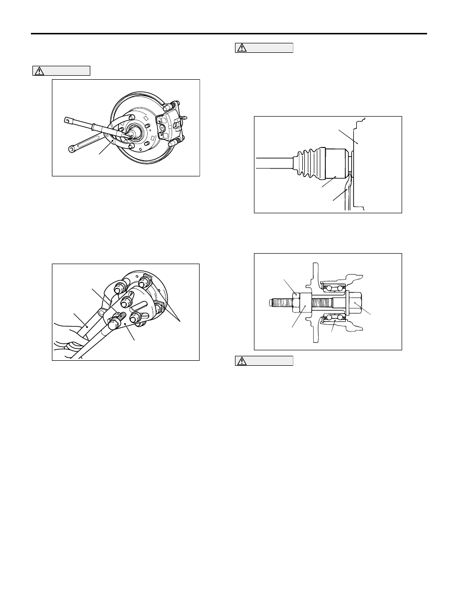
<<A>> DRIVE SHAFT NUT REMOVAL

CAUTION

Do not apply pressure to wheel bearing by the 
vehicle weight to avoid possible damage to 
wheel bearing before tightening drive shaft nut 
fully.
Use special tool end yoke holder (MB990767) to fix 
the hub and remove the drive shaft nut.

<<B>> DRIVE SHAFT REMOVAL

1. Use the following special tools to push out the 

drive shaft from the hub.

Puller shaft (MB990242)

Puller bar (MB990244)

Puller body (MB991354)

End yoke holder (MB990767)

CAUTION

Do not pull on the drive shaft; doing so will 
damage the TJ; be sure to use the pry bar.

When pulling the drive shaft out from the 
differential carrier, be careful that the spline 
part of the drive shaft does not damage the oil 
seal.

2. Remove the drive shaft from the differential carrier 

by using a pry bar.

CAUTION

Do not apply pressure to the wheel bearing by 
the vehicle weight to avoid possible damage 
when the drive shaft is removed. If, however, 
vehicle weight must be applied to the bearing in 
moving the vehicle, temporarily secure the wheel 
bearing by using the following special tools.

Front hub remover and installer (MB991017)

Spacer (MB991000)

AC201826

AC

MB990767

AC201827

MB991354

MB990244
(MB990241)

MB990242
(MB990241)

MB990767

AC

(Three)

AC102552 AE

TJ assembly

Pry bar

Differential carrier

AC102720

MB991000

MB991017

245 ± 29 N·m

AC

Wheel bearing

DRIVE SHAFT ASSEMBLY

REAR AXLE <4WD>

27B-12

INSTALLATION SERVICE POINTS

>>A<< DRIVE SHAFT INSTALLATION

CAUTION

When installing the drive shaft, be careful that 
the spline part of the drive shaft does not 
damage the oil seal.

>>B<< DRIVE SHAFT NUT INSTALLATION

CAUTION

Do not apply pressure to wheel bearing by the 
vehicle weight to avoid possible damage to 
wheel bearing before tightening drive shaft nut 
fully.

1. Assemble the drive shaft washer in the illustrated 

direction.

2. Tighten the drive shaft nut to the torque 

specification with special tool end yoke holder 
(MB990767).

INSPECTION

M1271003400069

Check the drive shaft for damage, bending or 
corrosion.

Check the drive shaft spline part for wear or 
damage.

Check the boots for deterioration, damage or 
cracking.

Check the dust cover for damage or 
deterioration.

AC201828

MB990767

245 ± 29 N·m

Washer

AC

DRIVE SHAFT ASSEMBLY

REAR AXLE <4WD>

27B-13

DISASSEMBLY AND REASSEMBLY

M1271003500185

CAUTION

Be careful not to damage the ABS rotor, which is attached to the BJ outer race during disassembly 
and reassembly.

Never disassemble the BJ assembly except when replacing the BJ boot.

AC201162

N

N

N

N

11

10

8

9

2

7

1

6

5

N

3

4

N

2

1

7

6

5

3

4

11

10

8

9

2

1

5

4

10

8

9

2

1

5

4

2

1

7

5

4

BJ repair kit

BJ boot repair kit

TJ boot repair kit

TJ repair kit

Grease for TJ

Grease for BJ

AB

Disassembly steps

>>C<<

1. TJ boot band (large)

>>C<<

2. TJ boot band (small)

<<A>> >>B<<

3. TJ case
4. Circlip
5. Snap ring

<<A>> >>B<<

6. Spider assembly

<<B>> >>A<<

7. TJ boot
8. BJ boot band (large)
9. BJ boot band (small)

<<B>> >>A<<

10. BJ boot
11. BJ assembly

Disassembly steps (Continued)

DRIVE SHAFT ASSEMBLY

REAR AXLE <4WD>

27B-14

LUIBRICATION POINTS

AC212165

Grease: repair kit grease
Amount used: 110 
± 10 g

CAUTION

Grease: repair kit grease
Amount used: 75 
± 10 g

The drive shaft joint uses special 
grease. Do not mix old and new or
different types of grease.

CAUTION

The drive shaft joint uses special 
grease. Do not mix old and new or
different types of grease.

AC


Content   ..  233  234  235  236   ..