Mitsubishi Outlander (2003+). Manual - part 227
FRONT AXLE HUB ASSEMBLY
FRONT AXLE
26-13
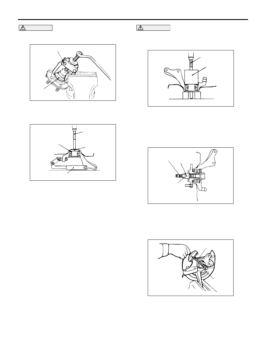
CAUTION
When removing the inner race (outside) from the
hub, be careful not to let the hub drop.
2. Remove the wheel bearing inner race (outside)
from the front hub by using special tool side
bearing puller (MB990810).
3. Install the inner race (outside) that was removed
from the hub to the wheel bearing, and then use
the following special tools to remove the wheel
bearing.
•
Installer bar (MB990938)
•
Installer adapter (MB990935)
•
Knuckle arm bridge (MB991056 or MB991355)
REASSEMBLY SERVICE POINTS
>>A<< WHEEL BEARING INSTALLATION
1. Fill the wheel bearing with multipurpose grease.
2. Apply a thin coating of multipurpose grease to the
knuckle and bearing contact surfaces.
CAUTION
Press the outer race when pressing-in the wheel
bearing. Otherwise the wheel bearing will be
damaged.
3. Press-in the bearing by using the following special
tools.
•
Rear suspension bushing arbor (MB990833)
•
Rear suspension bushing base (MB990890)
>>B<< HUB STARTING TORQUE CHECK
1. Tighten the following special tools to the specified
torque, and then press-in the hub into the knuckle.
•
Front hub remover and installer (MB991017)
•
Spacer (MB991000)
2. Rotate the hub in order to seat the bearing.
3. Measure the hub starting torque by using the
following special tools.
•
Torque wrench (MB990685)
•
Preload socket (MB990326)
Limit: 1.8 N
⋅
m
AC102509
MB990810
Inner race
(outside)
AC
AC102510 AC
MB990938
MB990935
MB991056 or MB991355
Inner race
(outside)
AC102511
MB990883
MB990890
AC
AC210929 AC
MB991000
MB991017
245 ± 29 N·m
Tighten the nut
with the bolt secured
AC100136
MB990685
MB990326
AB