Mitsubishi Outlander (2003+). Manual - part 199


  Index      Mitsubishi     Mitsubishi Outlander - service repair manual 2003 year


Search            


Content   ..  197  198  199  200   ..


Mitsubishi Outlander (2003+). Manual - part 199


TROUBLESHOOTING <A/T>

AUTOMATIC TRANSMISSION (FF)

23A-91

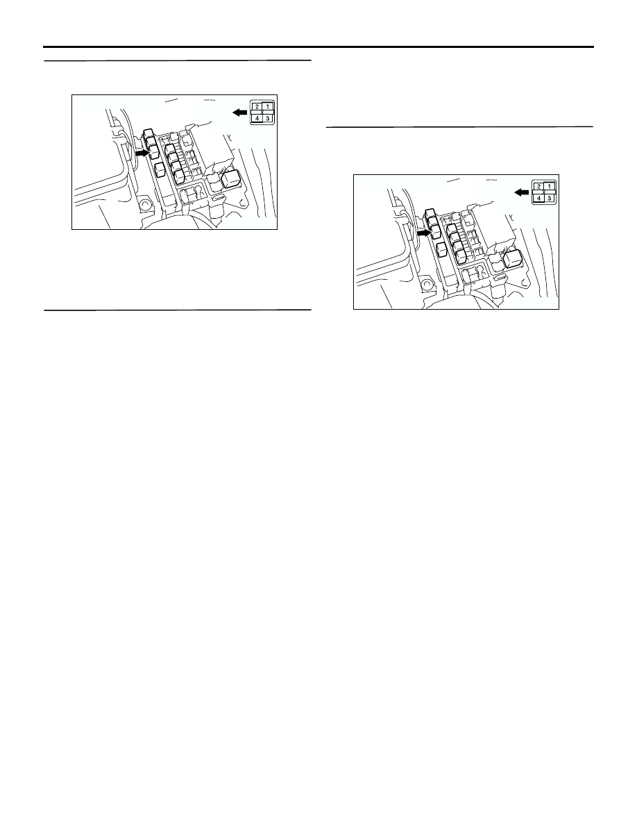
STEP 6. Check the harness between A/T control 
relay connector B-16X terminal No.4 and battery.

Check the power supply line for short or open circuit.

Q: Is the check result normal?

YES : 

Go to Step 7.

NO : 

Repair the wiring harness.

STEP 7. MUT-II/III data list

Item 54: Relay voltage (Refer to data list reference 
table 

P.23A-133

.)

Q: Is the check result normal?

YES : 

The trouble can be an intermittent 

malfunction (Refer to GROUP 00 

 How to 

Cope with Intermittent Malfunction 

P.00-6

).

NO : 

Replace the engine-A/T-ECU.

STEP 8. Measure the voltage at the A/T control 
relay connector B-16X.
(1) Turn the ignition switch to the ON position.

(2) Disconnect the A/T control relay, and measure 

the voltage between terminal No.3 and earth at 
the relay box side.

OK: System voltage

Q: Is the check result normal?

YES : 

Go to Step 11.

NO : 

Go to Step 9.

AC309525

AB

Connector: B-16X

Front of 
vehicle

Relay box 
side

AC309525

AB

Connector: B-16X

Front of 
vehicle

Relay box 
side

TROUBLESHOOTING <A/T>

AUTOMATIC TRANSMISSION (FF)

23A-92

STEP 9. Connectors check: C-16 J/C (1), C-106 
intermediate connector, C-202 J/B connector

Check for the contact with terminals.

Q: Is the check result normal?

YES : 

Go to Step 10.

NO : 

Repair the defective connector.

AC308736

C-16 (L)

AX

C-106 (GR)

Connectors: C-16, C-106
<RHD>

C-16

C-106

11

22

10

21

9

20

8

19

7

18

6

17

5

16

4

15

3

14

2

13

1

12

13

3

7

16

19

15

14

18

17

12

6

4

8

1

9

11

10

5

2

Haness side

AC308719

C-16 (L)

AU

Connectors: C-16, C-106
<LHD>

C-106

C-16

C-106 (GR)

11

22

10

21

9

20

8

19

7

18

6

17

5

16

4

15

3

14

2

13

1

12

13

3

7

16

19

15

14

18

17

12

6

4

8

1

9

11

10

5

2

Harness side

AC308772

C-202

Harness side

10

1

6

14

5

12

13

4

11

7

2

3

8

9

Connector: C-202
<RHD>

AL

AC308720

C-202

Harness side

10

1

6

14

5

12

13

4

11

7

2

3

8

9

AM

Connector: C-202
<LHD>

TROUBLESHOOTING <A/T>

AUTOMATIC TRANSMISSION (FF)

23A-93

STEP 10. Check the wiring harness between A/T 
control relay connector B-16X terminal No.3 and 
junction block connector C-202 terminal No.12.

Check the power supply line for short or open circuit.

Q: Is the check result normal?

YES : 

Go to Step 7.

NO : 

Repair the wiring harness.

STEP 11. Measure the voltage at engine-A/T-ECU 
connector C-138.
(1) Install the A/T control relay.
(2) Turn the ignition switch to the ON position.

(3) Measure the voltage between engine-A/T-ECU 

connector C-138 terminal No.123, No.124 and 
earth.

OK: System voltage

Q: Is the check result normal?

YES : 

Go to Step 14.

NO : 

Go to Step 12.

AC309525

AB

Connector: B-16X

Front of 
vehicle

Relay box 
side

AC308772

C-202

Harness side

10

1

6

14

5

12

13

4

11

7

2

3

8

9

Connector: C-202
<RHD>

AL

AC308720

C-202

Harness side

10

1

6

14

5

12

13

4

11

7

2

3

8

9

AM

Connector: C-202
<LHD>

AC309479

Engine-A/T-ECU

Harness side

C-138 (GR)

Engine-A/T-ECU

C-138 (GR)

124 123

130

131

132

133
141 140 139 138
146 145

129
137

128
136

127126

135
143

121
125
134
142

144

122

AC

Connector: C-138 <RHD>

Connector: C-138 <LHD>

TROUBLESHOOTING <A/T>

AUTOMATIC TRANSMISSION (FF)

23A-94

STEP 12. Connector check: C-138 
engine-A/T-ECU connector

Check for the contact with terminals.

Q: Is the check result normal?

YES : 

Go to Step 13.

NO : 

Repair the defective connector.

STEP 13. Check the harness between A/T control 
relay connector B-16X terminal No.1 and 
engine-A/T-ECU connector C-138 terminal 
No.123, 124.

Check the power supply line for short or open circuit.

Q: Is the check result normal?

YES : 

Go to Step 7.

NO : 

Repair the wiring harness.

AC309479

Engine-A/T-ECU

Harness side

C-138 (GR)

Engine-A/T-ECU

C-138 (GR)

124 123

130

131

132

133
141 140 139 138
146 145

129
137

128
136

127126

135
143

121
125
134
142

144

122

AC

Connector: C-138 <RHD>

Connector: C-138 <LHD>

AC309525

AB

Connector: B-16X

Front of 
vehicle

Relay box 
side

AC309479

Engine-A/T-ECU

Harness side

C-138 (GR)

Engine-A/T-ECU

C-138 (GR)

124 123

130

131

132

133
141 140 139 138
146 145

129
137

128
136

127126

135
143

121
125
134
142

144

122

AC

Connector: C-138 <RHD>

Connector: C-138 <LHD>


Content   ..  197  198  199  200   ..