Mitsubishi Outlander (2003+). Manual - part 193
TROUBLESHOOTING <A/T>
AUTOMATIC TRANSMISSION (FF)
23A-67
STEP 5. Measure the voltage at engine-A/T-ECU
connector C-138.
(1) Connect A/T control solenoid valve assembly
connector B-34.
(2) Turn the ignition switch to the ON position.
(3) Measure the voltage between engine-A/T-ECU
connector C-138 terminal No.128 and earth.
OK: System voltage
Q: Is the check result normal?
YES :
Go to Step 8.
NO :
Go to Step 6.
STEP 6. Connector check: C-138 engine-A/T-ECU
connector
Check for the contact with terminals.
Q: Is the check result normal?
YES :
Go to Step 7.
NO :
Repair the defective connector.
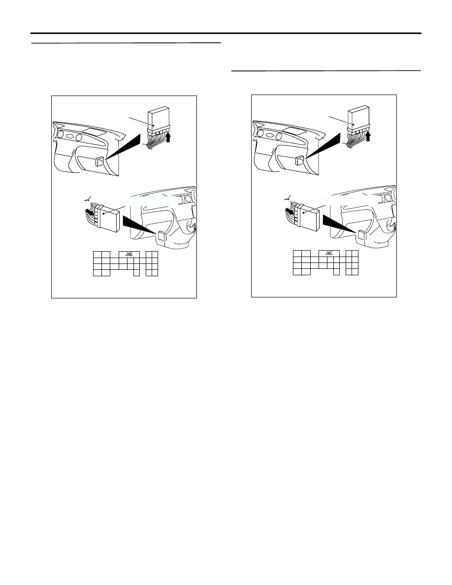
AC309479
Engine-A/T-ECU
Harness side
C-138 (GR)
Engine-A/T-ECU
C-138 (GR)
124 123
130
131
132
133
141 140 139 138
146 145
129
137
128
136
127126
135
143
121
125
134
142
144
122
AC
Connector: C-138 <RHD>
Connector: C-138 <LHD>
AC309479
Engine-A/T-ECU
Harness side
C-138 (GR)
Engine-A/T-ECU
C-138 (GR)
124 123
130
131
132
133
141 140 139 138
146 145
129
137
128
136
127126
135
143
121
125
134
142
144
122
AC
Connector: C-138 <RHD>
Connector: C-138 <LHD>