Mitsubishi Outlander (2003+). Manual - part 185


  Index      Mitsubishi     Mitsubishi Outlander - service repair manual 2003 year


Search            


Content   ..  183  184  185  186   ..


Mitsubishi Outlander (2003+). Manual - part 185


TROUBLESHOOTING <A/T>

AUTOMATIC TRANSMISSION (FF)

23A-35

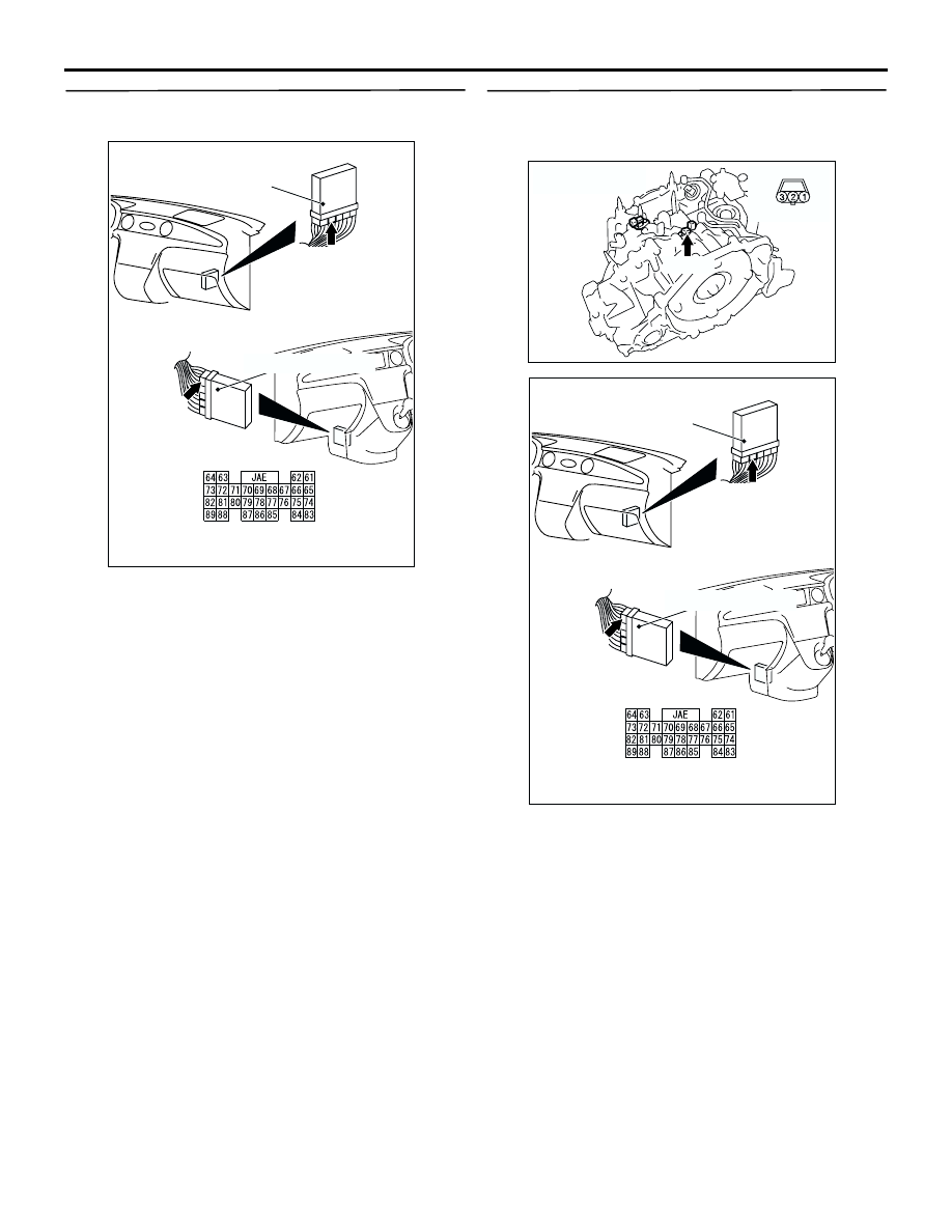
STEP 16. Connector check: C-141 
engine-A/T-ECU connector 

Check for the contact with terminals.

Q: Is the check result normal?

YES : 

Go to Step 17.

NO : 

Repair the defective connector.

STEP 17. Check the harness between input shaft 
speed sensor connector B-36 terminal No.2 and 
engine-A/T-ECU connector C-141 terminal No.64.

Check the output line for open circuit.

Q: Is the check result normal?

YES : 

Go to Step 6.

NO : 

Repair the wiring harness.

AC309479 AE

Connector: C-141 <LHD>

Connector: C-141 <RHD>

Engine-A/T-ECU

Harness side

Engine-A/T-ECU

C-141 (GR)

C-141 (GR)

AC309512 AB

B-36 (B)

Connector: B-36

Harness side

AC309479 AE

Connector: C-141 <LHD>

Connector: C-141 <RHD>

Engine-A/T-ECU

Harness side

Engine-A/T-ECU

C-141 (GR)

C-141 (GR)

TROUBLESHOOTING <A/T>

AUTOMATIC TRANSMISSION (FF)

23A-36

STEP 18. Measure the output wave pattern of the 
input shaft speed sensor at engine-A/T-ECU 
connector C-141 (using an oscilloscope).
(1) Shift the selector lever to the D range.
(2) Accelerate the vehicle to approximately 50 km/h 

(shift range; 3rd).

(3) Connect an oscilloscope, and measure the 

voltage between engine-A/T-ECU connector 
C-141 terminal No.64 and earth.

OK: A wave pattern such as the one 
shown on 

P.23A-139

 (Check Procedure 

Using an Oscilloscope) should be output, 
and the maximum value should be 4.8 V 
or more and the minimum value should 
be 0.8 V or less. There should be no noise 
in the output wave pattern.

Q: Is the check result normal?

YES : 

Go to Step 6.

NO : 

Go to Step 19.

STEP 19. Connector check: C-141 
engine-A/T-ECU connector

Check for the contact with terminals.

Q: Is the check result normal?

YES : 

Go to Step 20.

NO : 

Repair the defective connector.

STEP 20. Replace the input shaft speed sensor 
and then recheck the diagnosis code.
(1) Replace the input shaft speed sensor.
(2) Test drive the vehicle.
(3) Check if the diagnosis code is set.

Q: Is diagnosis code 22 set?

YES : 

Go to Step 21.

NO : 

The inspection is complete.

STEP 21. Underdrive clutch retainer inspection

Visually check the underdrive clutch retainer for 
damage.

Q: Is the check result normal?

YES : 

Eliminate the cause of the noise.

NO : 

Replace the underdrive clutch retainer.

AC309479 AE

Connector: C-141 <LHD>

Connector: C-141 <RHD>

Engine-A/T-ECU

Harness side

Engine-A/T-ECU

C-141 (GR)

C-141 (GR)

AC309479 AE

Connector: C-141 <LHD>

Connector: C-141 <RHD>

Engine-A/T-ECU

Harness side

Engine-A/T-ECU

C-141 (GR)

C-141 (GR)

TROUBLESHOOTING <A/T>

AUTOMATIC TRANSMISSION (FF)

23A-37

Code No.23: Output shaft speed sensor system

ENGINE-
A/T-ECU

OUTPUT SHAFT
SPEED SENSOR 

IGNITION
SWITCH (IG1)

Wire colour code
B : Black     LG : Light green     G : Green     L : Blue     W : White     Y : Yellow     SB : Sky blue
BR : Brown     O : Orange     GR : Gray     R : Red     P : Pink     V : Violet   

AC309574AC

Output shaft speed sensor system circuit

TROUBLESHOOTING <A/T>

AUTOMATIC TRANSMISSION (FF)

23A-38

OPERATION
The output shaft speed sensor detects the speed of 
the transfer drive gear, and sends the information to 
the engine-A/T-ECU as a pulse signal.

diagnosis code set conditions
If the output pulse from the output shaft speed 
sensor has been lost for one second or more while 
the vehicle is being driven, it is judged that there is 
an open circuit or short circuit in the output shaft 
speed sensor, and diagnosis code 23 is set.
If the code No. 23 is set four times, the transmission 
will be fixed in 3rd gear as a fail-safe measure. 
However, the transmission can be downshifted to 
2nd gear by operating the selector lever. 

Possible causes

Malfunction of output shaft speed sensor

Malfunction of transfer drive gear or driven gear

Damaged harness wires and connectors

Malfunction of the engine-A/T-ECU

DIAGNOSIS

STEP 1. MUT-II/III data list

Item 23: Output shaft speed sensor (Refer to data list 
reference table 

P.23A-133

). 

Q: Is the check result normal?

YES : 

Intermittent malfunction (Refer to GROUP 

00 

 How to Cope with Intermittent 

Malfunction 

P.00-6

).

NO : 

Go to Step 2.

STEP 2. Connector check: B-33 output shaft 
speed sensor connector

Check for the contact with terminals.

Q: Is the check result normal?

YES : 

Go to Step 3.

NO : 

Repair the defective connector.

STEP 3. Measure the resistance at output shaft 
speed sensor connector B-33.

Disconnect the connector, and measure the 
resistance between terminal 1 and earth at the wiring 
harness side.

OK: 2 

 or less

Q: Is the check result normal?

YES : 

Go to Step 9.

NO : 

Go to Step 4.

AC309512 AD

B-33 (GR)

Connector: B-33

Harness side

AC309512 AD

B-33 (GR)

Connector: B-33

Harness side


Content   ..  183  184  185  186   ..