Mitsubishi Outlander (2003+). Manual - part 168
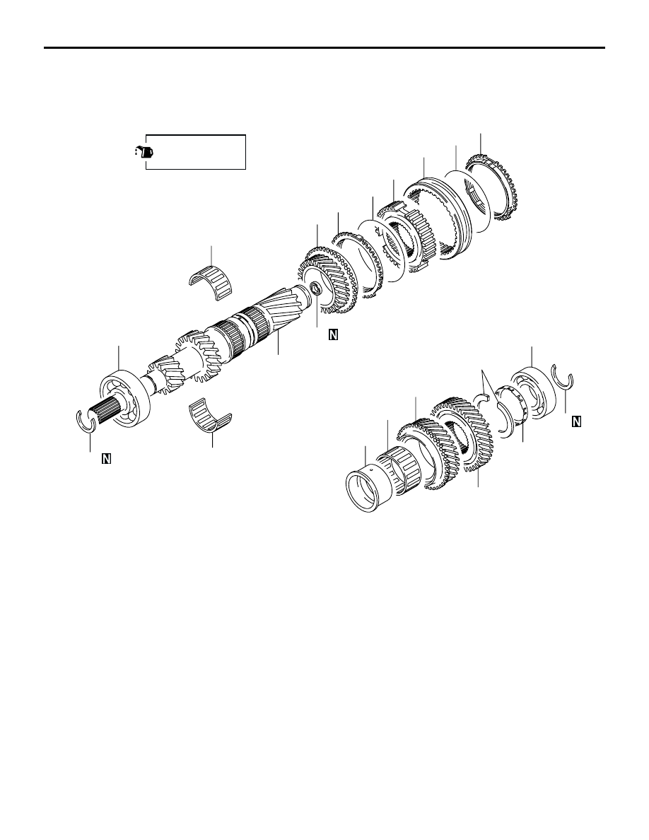
INPUT SHAFT
MANUAL TRANSMISSION OVERHAUL
22B-25
INPUT SHAFT
DISASSEMBLY AND REASSEMBLY
M1222001600173
AK204391
9
10
11
12
14
13
15
16
18
2
19
4
20
6
7
1
8
3
17
16
5
AB
AB
Apply gear oil to all
moving parts before
installation.
Disassembly steps
>>M<<
1.
Snap ring
<<A>>
>>L<<
2.
Ball bearing
<<B>>
>>K<<
3.
Thrust plate stopper
>>J<<
4.
Thrust plate
<<C>>
>>I<<
5.
5th speed gear
6.
4th speed gear
7.
Needle roller bearing
<<D>>
>>H<<
8.
4th speed gear sleeve
>>E<<
9.
Synchronizer ring
>>D<<
10. Synchronizer spring
>>G<<
11. Synchronizer sleeve
>>F<<
12. 3rd-4th speed synchronizer hub
>>E<<
13. Synchronizer ring
>>D<<
14. Synchronizer spring
15. 3rd speed gear
16. Needle roller bearing
>>C<<
17. Snap ring
<<E>>
>>B<<
18. Ball bearing
>>A<<
19. Oil seal
20. Input shaft
Disassembly steps (Continued)