Mitsubishi Outlander (2003+). Manual - part 125
 

  Index      Mitsubishi     Mitsubishi Outlander - service repair manual 2003 year


Search            


Content   ..  123  124  125  126   ..


Mitsubishi Outlander (2003+). Manual - part 125


TROUBLESHOOTING

ENGINE COOLING

14-11

STEP 21. Check the harness wire between fan 
controller connector A-20 terminal 2 and 
engine-ECU or engine-A/T-ECU connector C-134 
terminal 21 <4G63> or C-139 terminal 17 <4G69>.

Q: Are these harness wires in good condition?

YES : 

Go to Step 22.

NO : 

Repair the damaged harness wire. Then go 
to Step 24.

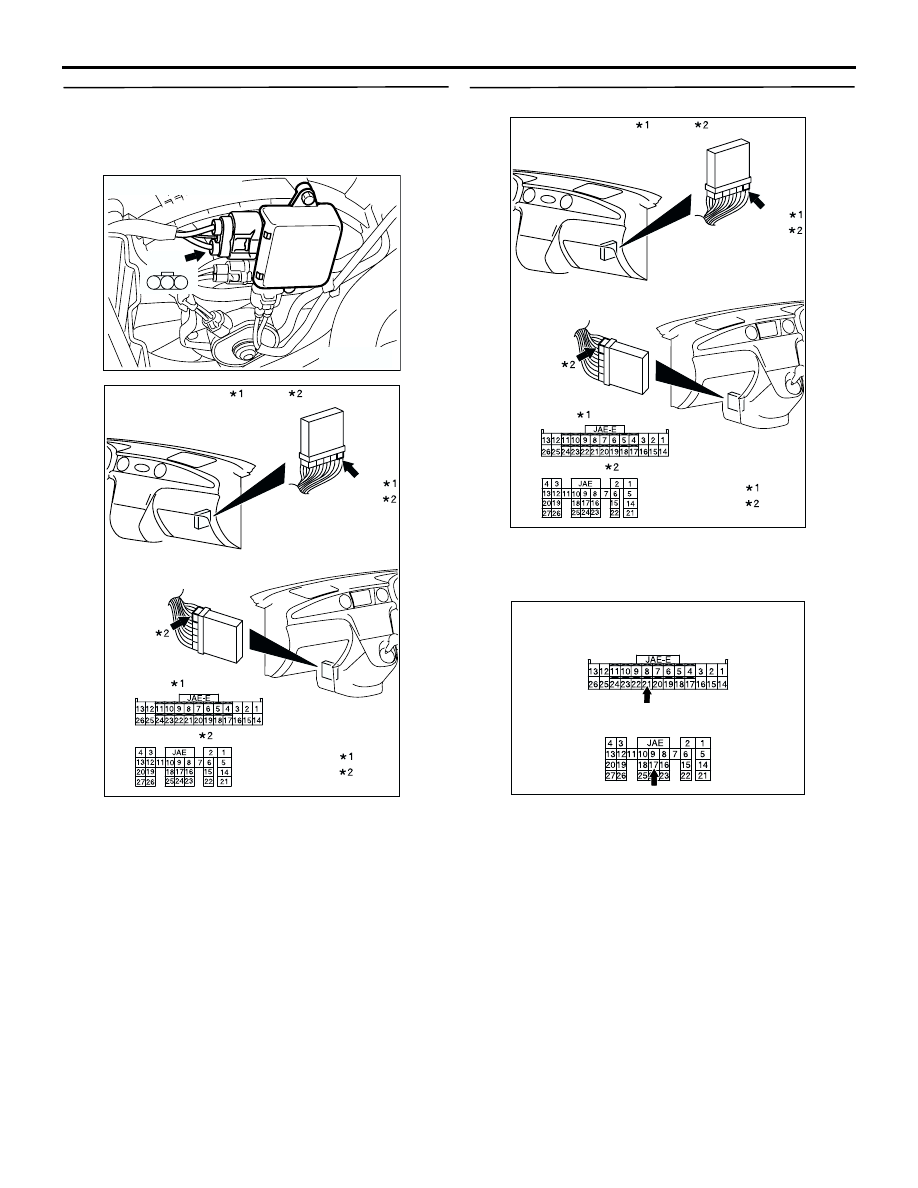
STEP 22. Check the fan controller.

(1) Disconnect engine-ECU connector or 

engine-A/T-ECU connector C-134 <4G63> or 
C-139 <4G69>.

(2) Pull out connector terminal pin 21 <4G63> or 17 

<4G69> to disconnect connector.

(3) Reconnect the connector with connector terminal 

pin still removed.

(4) Turn the ignition switch to the "ON" position.
(5) Check for the cooling fan operation.

•

The cooling fan rotates. (with connector 
terminal pin 21 <4G63> or 17 <4G69> 
disconnected)

•

The cooling fan stops. (When connector 
terminal pin 21 <4G63> or 17 <4G69> is 
connected to the body earth.)

(6) Turn the ignition switch to the "OFF" position.

AC301902

3

2

1

A-20

Connector: A-20

AB

AC309503

Connectors: C-134    , C-139

: 4G63
: 4G69

<L.H. drive vehicles>

<R.H. drive vehicles>

C-134
C-139

C-139

C-134     Harness side

C-139(GR)     Harness side

AB

AC309503

Connectors: C-134    , C-139

: 4G63
: 4G69

<L.H. drive vehicles>

<R.H. drive vehicles>

C-134
C-139

C-139

C-134     Harness side

C-139(GR)     Harness side

AB

AC309522

C-139 connector <4G69>
(Harness side connector: ECU side view)

AB

C-134 connector <4G63>
(Harness side connector: ECU side view)

TROUBLESHOOTING

ENGINE COOLING

14-12

(7) Disconnect engine-ECU connector or 

engine-A/T-ECU connector C-134 <4G63> or 
C-139 <4G69>, and push in connector terminal 
pin 21 <4G63> or 17 <4G69> to disconnect 
connector.

(8) Reconnect the connector with connector terminal 

pin still installed.

Q: Does the cooling fan rotate? And when the 

connector terminal pin is connected to the body 
earth, does the cooling fan stop?

YES : 

Go to Step 23.

NO : 

Replace the fan controller (Refer to 

P.14-29

). Then go to Step 24.

STEP 23. MUT-II/III self-diag code

Check if an MPI system self-diag code is set. (Refer 
to GROUP 13A - Trouble shooting 

P.13A-9

) <4G63> 

or (Refer to GROUP 13B - Trouble shooting 

P.13B-10

) <4G69>.

Q: Diagnosis code set?

YES : 

Inspection chart for diagnosis code (Refer 

to GROUP 13A - Trouble shooting 

P.13A-16

) <4G63> or Inspection chart for 

diagnosis code (Refer to GROUP 13B - 
Trouble shooting 

P.13B-20

) <4G69>.

NO : 

Replace the engine-ECU <M/T> or 
engine-A/T-ECU <A/T> (Refer to GROUP 
13A, Engine-ECU 

P.13A-343

) <4G63> or 

(Refer to GROUP 13B, Engine-ECU and 
Engine-A/T-ECU 

P.13B-439

) <4G69>. Then 

go to Step 24.

STEP 24. Check the symptoms.

Q: Does the radiator fan motor and the condenser fan 

motor operate correctly?

YES : 

This symptoms is complete.

NO : 

Return to Step 1.

INSPECTION PROCEDURE 2: Radiator Fan and Condenser Fan do not Change Speed or Stop

Radiator Fan and Condenser Fan Drive Circuit
Refer to 

P.14-4

.

TECHNICAL DESCRIPTION

•

The cause could be a malfunction of the fan 
controller power supply or earth circuit.

•

If the communication line wiring harness between 
the fan controller and the engine-ECU <M/T> or 
engine-A/T-ECU <A/T> is short-circuited to earth, 
the radiator fan motor and the condenser fan 
motor will not rotate.

•

The cause could also be a malfunction of input 
signal from the A/C switch, the water temperature 
sensor unit and the vehicle speed sensor <M/T> 
or the output shaft speed sensor <A/T> to the 
engine-ECU <M/T> or engine-A/T-ECU <A/T>.

•

The cause could also be a malfunction of the fan 
controller or the engine-ECU <M/T> or 
engine-A/T-ECU <A/T>.

TROUBLESHOOTING HINTS

•

Malfunction of fusible link No.2

•

Malfunction of fan control relay

•

Malfunction of cooling fan motor

•

Malfunction of fan controller

•

Malfunction of engine-ECU <M/T> or 
engine-A/T-ECU <A/T>

•

Damaged wiring harness or connector

DIAGNOSIS

STEP 1. Check the fan control relay.

Refer to 

P.14-19

.

Q: Is the fan control relay in good condition?

YES : 

Go to Step 2.

NO : 

Replace the fan control relay. Then go to 
Step 8.

STEP 2. Check the fan control relay connector 
A-10X.

Q: Is the connector in good condition?

YES : 

Go to Step 3.

NO : 

Repair the connector or replace the relay 
box. Then go to Step 8.

AC309505 AC

Fan control relay

Relay box

Connector: A-10X

A-10X

TROUBLESHOOTING

ENGINE COOLING

14-13

STEP 3. Check the harness wire between fan 
control relay connector A-10X terminal 2 and fan 
controller connector A-20 terminal 3.

Q: Is the harness wire in good condition?

YES : 

Go to Step 4.

NO : 

Repair the damaged harness wire. Then go 
to Step 8.

STEP 4. Check the fan controller connector A-20, 
intermediate connector A-14 and engine-ECU 
connector or engine-A/T-ECU connector C-134 
<4G63> or C-139 <4G69>.

Q: Are these connectors in good condition?

YES : 

Go to Step 5.

NO : 

Repair or replace the connector. Then go to 
Step 8.

AC309505 AC

Fan control relay

Relay box

Connector: A-10X

A-10X

AC301902

3

2

1

A-20

Connector: A-20

AB

AC301902

3

2

1

A-20

Connector: A-20

AB

AC309506

Connector: A-14

A-14(GR)

A-14(GR)

AB

AC309503

Connectors: C-134    , C-139

: 4G63
: 4G69

<L.H. drive vehicles>

<R.H. drive vehicles>

C-134
C-139

C-139

C-134     Harness side

C-139(GR)     Harness side

AB

TROUBLESHOOTING

ENGINE COOLING

14-14

STEP 5. Check the harness wire between fan 
controller connector A-20 terminal 2 and 
engine-ECU connector or engine-A/T-ECU 
connector C-134 terminal 21 <4G63> or C-139 
terminal 17 <4G69>.

Q: Are these harness wires in good condition?

YES : 

Go to Step 6.

NO : 

Repair the damaged harness wire. Then go 
to Step 8.

STEP 6. Check the fan controller.

(1) Disconnect engine-ECU connector or 

engine-A/T-ECU connector C-134 <4G63> or 
C-139 <4G69>.

(2) Pull out connector terminal pin 21 <4G63> or 17 

<4G69> to disconnect connector.

(3) Reconnect the connector with connector terminal 

pin still removed.

(4) Turn the ignition switch to the "ON" position.
(5) Check for the cooling fan operation.

•

The cooling fan rotates. (with connector 
terminal pin 21 <4G63> or 17 <4G69> 
disconnected)

•

The cooling fan stops. (When connector 
terminal pin21 <4G63> or 17 <4G69> is 
connected to the body earth.)

(6) Turn the ignition switch to the "OFF" position.

AC301902

3

2

1

A-20

Connector: A-20

AB

AC309503

Connectors: C-134    , C-139

: 4G63
: 4G69

<L.H. drive vehicles>

<R.H. drive vehicles>

C-134
C-139

C-139

C-134     Harness side

C-139(GR)     Harness side

AB

AC309503

Connectors: C-134    , C-139

: 4G63
: 4G69

<L.H. drive vehicles>

<R.H. drive vehicles>

C-134
C-139

C-139

C-134     Harness side

C-139(GR)     Harness side

AB

AC309522

C-139 connector <4G69>
(Harness side connector: ECU side view)

AB

C-134 connector <4G63>
(Harness side connector: ECU side view)


Content   ..  123  124  125  126   ..