Mitsubishi Outlander (2003+). Manual - part 99


  Index      Mitsubishi     Mitsubishi Outlander - service repair manual 2003 year


Search            


Content   ..  97  98  99  100   ..


Mitsubishi Outlander (2003+). Manual - part 99


TROUBLESHOOTING

MULTIPORT FUEL INJECTION (MFI)

13A-259

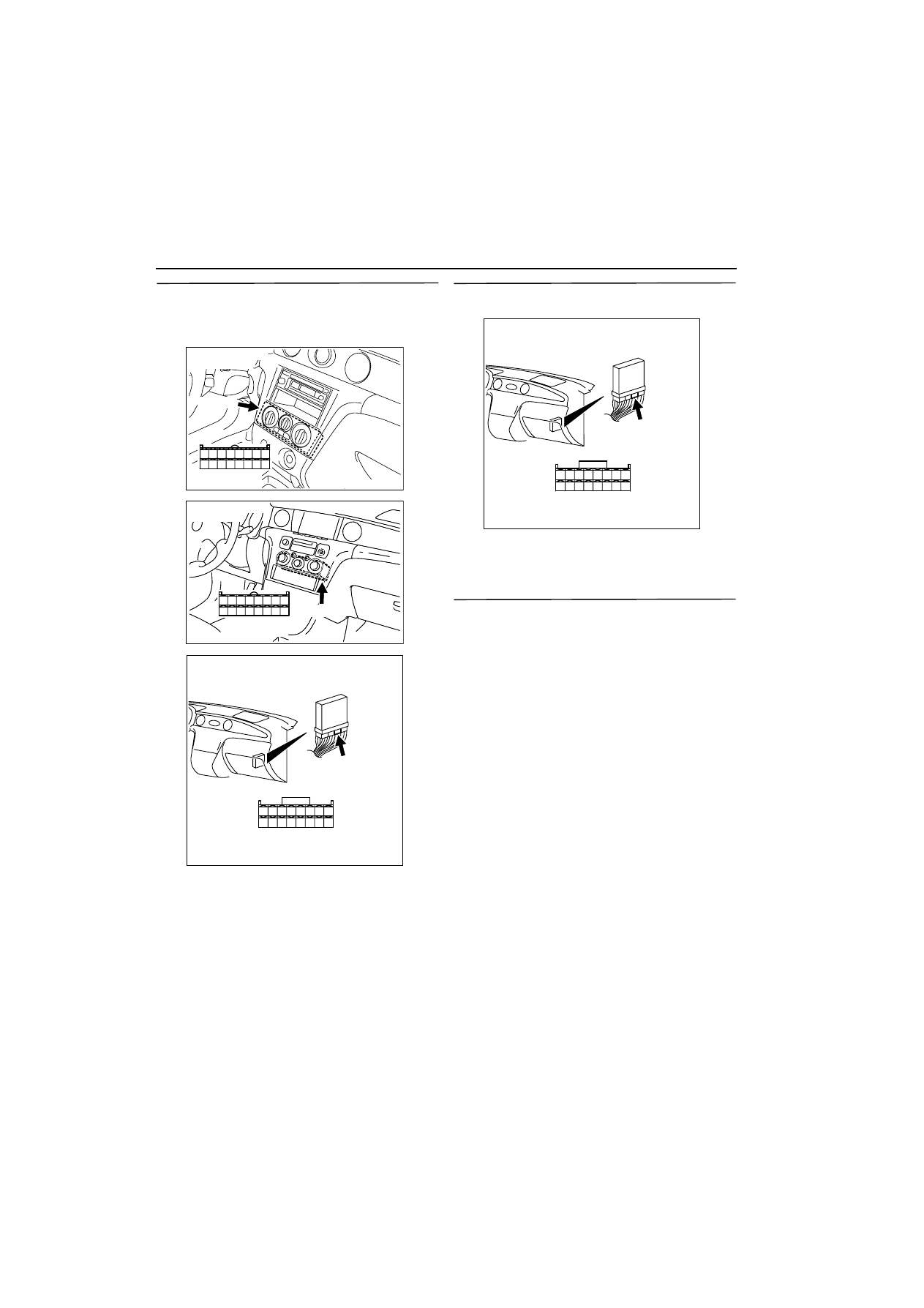
STEP 5. Connector check: C-06 A/C-ECU 
connector <Manual A/C> or C-26 A/C-ECU 
connector <Auto A/C> and C-135 engine-ECU 
connector

Q: Is the check result normal?

YES : 

Check intermediate connector C-104, and 

repair if necessary. If intermediate 
connector is normal, check and repair 
harness between C-06 (terminal No. 4) or 
C-26 (terminal No. 34) A/C-ECU connector 
and C-135 (terminal No. 45) engine-ECU 
connector.

œ

Check output line for open circuit.

NO : 

Repair.

STEP 6. Connector check: C-135 engine-ECU 
connector

Q: Is the check result normal?

YES : 

Go to Step 7 .

NO : 

Repair.

STEP 7. MUT-II data list

œ

Item 28: A/C switch

a. Engine: Idling
b. A/C set temperature: 

Maximum Cool when temperature in cabin is 

25

•

C or more.

Maximum Hot when temperature in cabin is 

25

•

C or less.

OK: 

ON (when A/C is ON)
OFF (when A/C is OFF)

Q: Is the check result normal?

YES : 

Intermittent malfunction (Refer to GROUP 

00 

-

 How to Use 

Troubleshooting/Inspection Service Points 

3

00


).

NO : 

Replace engine-ECU.

AK300326

8

16

7

15

6

14

5

13

4

12

3

11

2

10

1
9

Harness side
connector

C-06 (B)

AB

Connector: C-06
<Manual A/C>

AK300327

28
36

27
35

26
34

25
33

24
32

23
31

22
30

21
29

Harness side
connector

C-26 (B)

AB

Connector: C-26
<Auto A/C>

AK300256

34 33 32

36 35

37

42

45

31

39

38

46

40

41

43

44

AB

CONNECTOR: C-135

C-135

Harness side connector

AK300256

34 33 32

36 35

37

42

45

31

39

38

46

40

41

43

44

AB

CONNECTOR: C-135

C-135

Harness side connector

TROUBLESHOOTING

MULTIPORT FUEL INJECTION (MFI)

13A-260

Inspection Procedure 27: A/C Compressor Relay System

3

4 5 6

1 2

1

2

3

4

1

1

14

4

19

5

22

6

17

8

15

9

18

7

20

16

2

13

12

23 24 25 26

21

3

10 11

AK300328

R

IG2

ST

LOCK

ACC

IG1

5

7.5A

10

10A

L-R

L-R

L-R

G

Ignition switch

C-303

4

C-203
2

C-205
16

C-106
11

J/B

A/C compressor relay

Engine-ECU

C-134

Battery

Relay box

B-R

B-W

B-R

W

4

3

1

1

2

B-18X

A/C-ECU

B-27

(MU802653)

A/C refrigerant 
temperature 
switch

A/C compressor 
assembly

Magnetic 
clutch

9

A-14

A/C compressor relay Circuit

8

Wire colour code
B: Black  LG: Light green  G: Green   L: Blue   W: White   Y: Yellow   SB: Sky blue   BR: Brown    O: Orange   GR: Gray
R: Red   P: Pink   V: Violet

AB

TROUBLESHOOTING

MULTIPORT FUEL INJECTION (MFI)

13A-261

OPERATION

œ

The battery voltage is applied to the A/C com-
pressor relay (terminal No. 4).

œ

The battery voltage is applied to the A/C com-
pressor relay (terminal No. 3) from the ignition 
switch. The engine-ECU (terminal No. 8) makes 
the power transistor in the unit be in "ON" posi-
tion and makes currents go on the A/C compres-
sor relay coil, and that makes the relay be in "ON" 
position.

œ

When the A/C compressor is in "ON" position, the 
battery voltage is supplied to the A/C compressor 
(terminal No. 1) from the A/C compressor relay 
(terminal No. 1).

FUNCTION

œ

When the A/C switch "ON" signal is input to the 
engine-ECU, the engine-ECU places the A/C 
compressor relay in the "ON" position. Accord-
ingly, the battery voltage supplied to the A/C com-
pressor operates the magnet clutch.

PROBABLE CAUSE

œ

Failed A/C compressor relay

œ

Failed A/C compressor magnet clutch

œ

Open/short circuit in A/C compressor relay circuit 
or loose connector contact

œ

Failed engine-ECU

DIAGNOSIS PROCEDURE

STEP 1. Connector check: B-18X A/C 
compressor relay connector

Q: Is the check result normal?

YES : 

Go to Step 2 .

NO : 

Repair.

STEP 2. A/C compressor relay check.

œ

Check A/C compressor relay (Refer to GROUP 
55A 

-

 On-vehicle Service 

3

55A


).

Q: Is the check result normal?

YES : 

Go to Step 3 .

NO : 

Replace A/C compressor relay.

STEP 3. Measure voltage at B-18X A/C 
compressor relay connector.

œ

Remove relay, and measure at relay box side.

œ

Ignition switch: ON

œ

Voltage between terminal No. 3 and earth.

OK: System voltage

Q: Is the check result normal?

YES : 

Go to Step 5 .

NO : 

Go to Step 4 .

AK300329

2

1

3

4

AB

CONNECTOR: B-18X

B-18X

Harness side
connector

Relay box’s
triangle marks

AK300329

2

1

3

4

AB

CONNECTOR: B-18X

B-18X

Harness side
connector

Relay box’s
triangle marks

TROUBLESHOOTING

MULTIPORT FUEL INJECTION (MFI)

13A-262

STEP 4. Connector check: C-303 ignition switch 
connector

Q: Is the check result normal?

YES : 

Check intermediate connectors C-106, C-

202 <Auto A/C>, C-203 and C-205 <Manual 
A/C>, and repair if necessary. If 
intermediate connectors are normal, check 
and repair harness between B-18X 
(terminal No. 3) A/C compressor relay 
connector and C-303 (terminal No. 4) 
ignition switch connector.

œ

Check power supply line for 
open/short circuit.

NO : 

Repair.

STEP 5. Measure voltage at B-18X A/C 
compressor relay connector.

œ

Remove relay, and measure at relay box side.

œ

Voltage between terminal No. 4 and earth.

OK: System voltage

Q: Is the check result normal?

YES : 

Go to Step 6 .

NO : 

Check intermediate connector A-14, and 

repair if necessary. If intermediate 
connector is normal, check and repair 
harness between B-18X (terminal No. 4) 
A/C compressor relay connector and 
battery.

œ

Check power supply line for 
open/short circuit.

STEP 6. Connector check: B-27 A/C compressor 
connector

Q: Is the check result normal?

YES : 

Go to Step 7 .

NO : 

Repair.

1

2

3

4

5

6

AK300304

CONNECTOR: C-303

C-303

Harness side
connector

AB

AK300329

2

1

3

4

AB

CONNECTOR: B-18X

B-18X

Harness side
connector

Relay box’s
triangle marks

AK300329

2

1

3

4

AB

CONNECTOR: B-18X

B-18X

Harness side
connector

Relay box’s
triangle marks

AK300330

1

AB

CONNECTOR: B-27

B-27 (B)

Harness side
connector


Content   ..  97  98  99  100   ..