Mitsubishi Outlander (2003+). Manual - part 73


  Index      Mitsubishi     Mitsubishi Outlander - service repair manual 2003 year


Search            


Content   ..  71  72  73  74   ..


Mitsubishi Outlander (2003+). Manual - part 73


TROUBLESHOOTING

MULTIPORT FUEL INJECTION (MFI)

13A-155

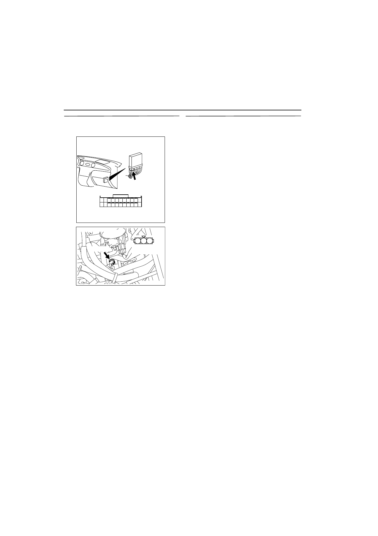
STEP 4.Check harness between C-137 (terminal 
No. 86) engine-ECU connector and B-115 
(terminal No. 3) Vehicle speed sensor connector.

NOTE: Before checking harness, check intermediate 
connector C-16, and repair if necessary.

œ

Check output line for open circuit and damage.

Q: Is the check result normal?

YES : 

Go to Step 5 .

NO : 

Repair.

STEP 5.Check the trouble symptoms.

Q: Does trouble symptom persist?

YES : 

 Replacing engine-ECU.

NO : 

Intermittent malfunction (Refer to GROUP 
00 - How to Use Troubleshooting/Inspection 
Service Points 

3

00


).

AK300254

82

78

8180

89

90

91

92

79

87

71

74 73 72

76 75

77

85

88

83

84

86

AB

CONNECTOR: C-137

C-137

Harness side connector

AK300285

1

2

3

AB

Harness side
connector

CONNECTOR: B-115

B-115 (B)

TROUBLESHOOTING

MULTIPORT FUEL INJECTION (MFI)

13A-156

Code No. P0505: Idle Speed Control Servo System

AK300286

1 2
4 5 6

3

1

2

3

4

1

14

4

19

5

22

6

17

8

15

9

18

7

20

16

2

13

12

23 24 25 26

21

3

10 11

AB

B-105

Idle speed control servo

B-17X

Engine control relay

1

L-Y

Y-L

W

G-Y

1

R

R

R

2

2

3

4

5

6

Engine-ECU

4

17

5

18

Idle speed control servo circuit

W-B

W-B

Battery

4

3

Wire colour code
B: Black  LG: Light green  G: Green  L: Blue  W: White  Y: Yellow  SB: Sky blue  BR: Brown  O: Orange  GR: Gray
R: Red  P: Pink  V:Violet

C-134

TROUBLESHOOTING

MULTIPORT FUEL INJECTION (MFI)

13A-157

OPERATION

œ

The power is supplied to the idle speed control 
servo (terminal No. 2 and No. 5) from the engine 
control relay (terminal No. 1).

œ

The engine-ECU (terminal No. 4, No. 5, No. 17 
and No. 18) makes power transistor in the unit be 
in "ON" position in order, and that makes currents 
go on the idle speed control servo (terminal No. 
1, No. 3, No. 4 and No. 6).

FUNCTION

œ

The idle speed control servo opens and closes 
the servo valve in response to a signal from the 
engine-ECU to control the intake air flow rate dur-
ing idling.

TROUBLE JUDGMENT

Check conditions

œ

The vehicle speed has reached 1.5 km/h or more 
at least once.

œ

During the closed-loop idle speed control.

Judgment Criteria

œ

The actual idle speed is higher than the target 
idle speed by 300 r/min or more for 10 seconds.

Check conditions

œ

The vehicle speed has reached 1.5 km/h or more 
at least once.

œ

During the closed-loop idle speed control.

œ

The highest ambient temperature at the last drive 
is 45 

•

C or less.

œ

The engine coolant temperature is approximately. 
82

•

C or higher.

œ

The battery voltage is 10 V or more.

œ

The intake air temperature is 

-

10

•

C or higher.

Judgment Criteria

œ

The actual idle speed is higher than the target 
idle speed by 200 r/min or more for 10 seconds.

Check conditions

œ

During the closed-loop idle speed control.

œ

The engine coolant temperature is approximately. 
82

•

C or higher.

œ

The battery voltage is 10 V or more.

œ

The power steering switch is in OFF position.

œ

The charging efficiency is 40 % or less.

œ

The intake air temperature is 

-

10

•

C or higher.

Judgment Criteria

œ

The actual idle speed is higher than the target 
idle speed by 100 r/min or more for 10 seconds.

PROBABLE CAUSE

œ

Failed idle speed control servo

œ

Open/short circuit in idle speed control servo cir-
cuit or loose connector contact

œ

Failed engine-ECU

DIAGNOSIS PROCEDURE

STEP 1. MUT-II Data List

œ

Refer to Data list reference table 

3

13A


.

a. Item 45: Idle speed control position

Q: Is the check result normal?

YES : 

Intermittent malfunction (Refer to GROUP 

00 

-

 How to Use 

Troubleshooting/Inspection Service Points 

3

00


).

NO : 

Go to Step 2 .

STEP 2. Connector check: B-105 idle speed 
control servo connector

Q: Is the check result normal?

YES : 

Go to Step 3 .

NO : 

Repair.

STEP 3. Check idle speed control servo itself.

œ

Check idle speed control servo itself (Refer to 

3

13A


).

Q: Is the check result normal?

YES : 

Go to Step 4 .

NO : 

Replace idle speed control servo.

1

2

3

4

5

6

AK300287

Harness side
connector

B-105 (B)

AB

Connector: B-105

TROUBLESHOOTING

MULTIPORT FUEL INJECTION (MFI)

13A-158

STEP 4. Measure voltage at B-105 idle speed 
control servo connector.

œ

Disconnect connector, and measure at harness 
side.

œ

Ignition switch: ON

œ

Voltage between terminal No. 2 and earth, also 
between terminal No. 5 and earth.

OK: System voltage

Q: Is the check result normal?

YES : 

Go to Step 6 .

NO : 

Go to Step 5 .

STEP 5. Check connector: B-17X engine control 
relay connector

Q: Is the check result normal?

YES : 

Check and repair harness between B-105 

(terminal No. 2 or No. 5) idle speed control 
servo connector and B-17X (terminal No. 1) 
engine control relay connector.

œ

Check power supply line for 
open/short circuit.

NO : 

Repair.

1

2

3

4

5

6

AK300287

Harness side
connector

B-105 (B)

AB

Connector: B-105

AK300255

2

1

3

4

Relay box’s
triangle marks

AB

CONNECTOR: B-17X

B-17X

Harness side
connector

1

2

3

4

5

6

AK300287

Harness side
connector

B-105 (B)

AB

Connector: B-105


Content   ..  71  72  73  74   ..