Mitsubishi Outlander (2003+). Manual - part 69


  Index      Mitsubishi     Mitsubishi Outlander - service repair manual 2003 year


Search            


Content   ..  67  68  69  70   ..


Mitsubishi Outlander (2003+). Manual - part 69


TROUBLESHOOTING

MULTIPORT FUEL INJECTION (MFI)

13A-139

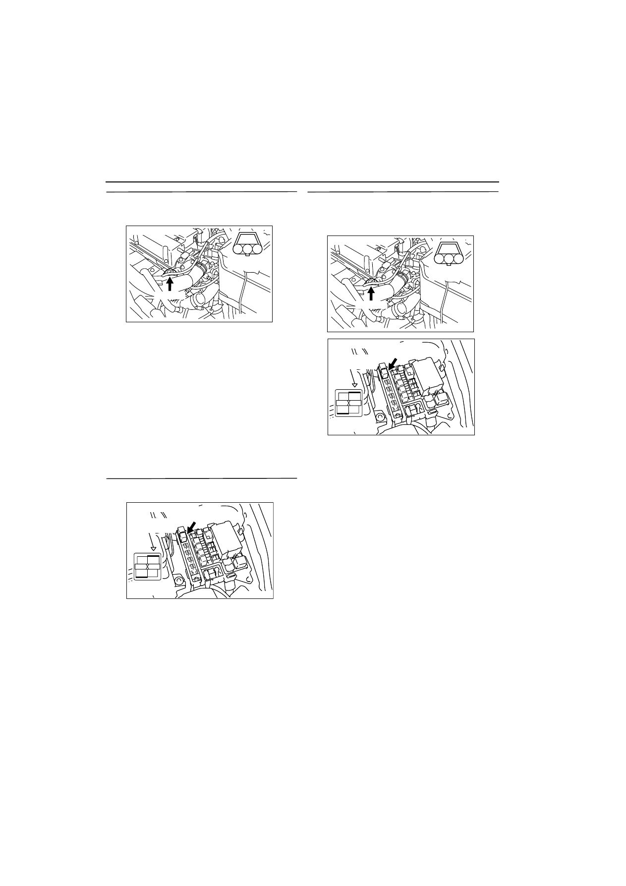
STEP 13. Measure output waveform at B-106 
camshaft position sensor connector (Use 
oscilloscope).

œ

Use special tool test harness (MB991709) to con-
nect connector, and measure at pick-up harness. 

œ

Engine: Idling

œ

Transmission: Neutral

œ

Voltage between terminal No. 2 and earth.

OK: Waveforms should be displayed on 
Inspection procedure using an oscilloscope 
(Refer to 

3

13A


), its maximum value 

should be 4.8 V or more, and its minimum 
value should be 0.6 V or less with no noise in 
waveform.

Q: Is the check result normal? 

YES : 

Go to Step 9 .

NO : 

Go to Step 14 .

STEP 14. Connector check: B-17X engine control 
relay connector.

Q: Is the check result normal? 

YES : 

Go to Step 15 .

NO : 

Repair.

STEP 15. Check harness between B-106 (terminal 
No. 3) camshaft position sensor connector and 
B-17X (terminal No. 1) engine control relay 
connector.

œ

Check power supply line for damage.

Q: Is the check result normal? 

YES : 

Go to Step 16 .

NO : 

Repair.

AK300279

1

2

3

Harness side
connector

B-106 (B)

AB

Connector: B-106

AK300255

2

1

3

4

Relay box’s
triangle marks

AB

CONNECTOR: B-17X

B-17X

Harness side
connector

AK300279

1

2

3

Harness side
connector

B-106 (B)

AB

Connector: B-106

AK300255

2

1

3

4

Relay box’s
triangle marks

AB

CONNECTOR: B-17X

B-17X

Harness side
connector

TROUBLESHOOTING

MULTIPORT FUEL INJECTION (MFI)

13A-140

STEP 16. Connector check: C-135 and C-137 
engine-ECU connectors

Q: Is the check result normal? 

YES : 

Go to Step 17 .

NO : 

Repair.

STEP 17. Check harness between B-106 (terminal 
No. 2) camshaft position sensor connector and 
C-137 (terminal No. 88) engine-ECU connector.

œ

Check output line for damage.

Q: Is the check result normal? 

YES : 

Go to Step 18 .

NO : 

Repair.

AK300277

34 33 32

36 35

37

42

45

31

39

38

46

40

41

43

44

82

78

8180

89

90

91

92

79

87

71

74 73 72

76 75

77

85

88

83

84

86

AB

CONNECTOR: C-135, C-137

C-135

C-137

C-137 Harness side connector

C-135 Harness side connector

AK300279

1

2

3

Harness side
connector

B-106 (B)

AB

Connector: B-106

AK300254

82

78

8180

89

90

91

92

79

87

71

74 73 72

76 75

77

85

88

83

84

86

AB

CONNECTOR: C-137

C-137

Harness side connector

TROUBLESHOOTING

MULTIPORT FUEL INJECTION (MFI)

13A-141

STEP 18. Check harness between B-106 (terminal 
No. 1) camshaft position sensor connector and 
C-135 (terminal No. 40) engine-ECU connector.

NOTE: Before checking harness, check intermediate 
connector C-16, and repair if necessary.

œ

Check earthing line for damage.

Q: Is the check result normal? 

YES : 

Go to Step 19 .

NO : 

Repair.

STEP 19. Check camshaft position sensing 
cylinder.

Q: Is the check result normal? 

YES : 

Go to Step 20 .

NO : 

Replace camshaft position sensing cylinder.

STEP 20. Check the trouble symptoms.

Q: Does trouble symptom persist?

YES : 

Replace camshaft position sensor.

NO : 

Intermittent malfunction (Refer to GROUP 
00 

-

 How to Use 

Troubleshooting/Inspection Service Points 

3

00


).

AK300279

1

2

3

Harness side
connector

B-106 (B)

AB

Connector: B-106

AK300256

34 33 32

36 35

37

42

45

31

39

38

46

40

41

43

44

AB

CONNECTOR: C-135

C-135

Harness side connector

TROUBLESHOOTING

MULTIPORT FUEL INJECTION (MFI)

13A-142

Code No. P0403: EGR Control Solenoid Valve System

OPERATION

œ

Power is supplied to the EGR control solenoid 
valve (terminal No. 1) from the engine control 
relay (terminal No. 1).

œ

The engine-ECU (terminal No. 6) makes the 
power transistor in the unit be in "ON", and that 
makes currents go on the EGR control solenoid 
valve (terminal No. 2).

AK300280

2

1

1

2

3

4

1

14

4

19

5

22

6

17

8

15

9

18

7

20

16

2

13

12

23 24 25 26

21

3

10 11

Engine control relay

B-17X

B-102

EGR control solenoid valve

1

1

2

2

76

Engine-ECU

EGR control solenoid valve circuit

W-B

L

R

W-B

Battery

4

3

Wire colour code
B: Black  LG: Light green  G: Green   L: Blue   W: White   Y: Yellow   SB: Sky blue   BR: Brown    O: Orange   GR: Gray
R: Red   P: Pink   V: Violet

AB

C-134


Content   ..  67  68  69  70   ..