Mitsubishi Outlander (2003+). Manual - part 60


  Index      Mitsubishi     Mitsubishi Outlander - service repair manual 2003 year


Search            


Content   ..  58  59  60  61   ..


Mitsubishi Outlander (2003+). Manual - part 60


TROUBLESHOOTING

MULTIPORT FUEL INJECTION (MFI)

13A-103

OPERATION

œ

Power is supplied to the injector (terminal No. 1) 
from the engine control relay (terminal No. 1).

œ

The engine-ECU (terminal No. 15) makes the 
power transistor in the unit be in "ON" position, 
and that makes currents go on the injector (termi-
nal No. 2).

FUNCTION

œ

The engine-ECU controls the power supply inter-
val of the injector.

œ

The fuel injection amount of the injector depends 
on the power supply interval.

TROUBLE JUDGMENT

Check Conditions

œ

The engine speed is 50 

-

 1,000 r/mim.

œ

The throttle position sensor output 1.15 V or less.

œ

Injector not in forced drive (actuator test) mode

Judgment Criterion

œ

No surge voltage of the injector coil is detected 
for 2 seconds

PROBABLE CAUSE

œ

Failed No. 4 injector

œ

Open/short circuit in No. 4 injector circuit or loose 
connector contact

œ

Failed engine-ECU 

DIAGNOSIS PROCEDURE

STEP 1. MUT-II actuator test

œ

Refer to Actuator test reference table list 

3

13A


.

a. Item 04: No. 4 injector

OK: Idling state varies.

Q: Is the check result normal?

YES : 

Intermittent malfunction (Refer to GROUP 

00 

-

 How to Use 

Troubleshooting/Inspection Service Points 

3

00


).

NO : 

Go to Step 2 .

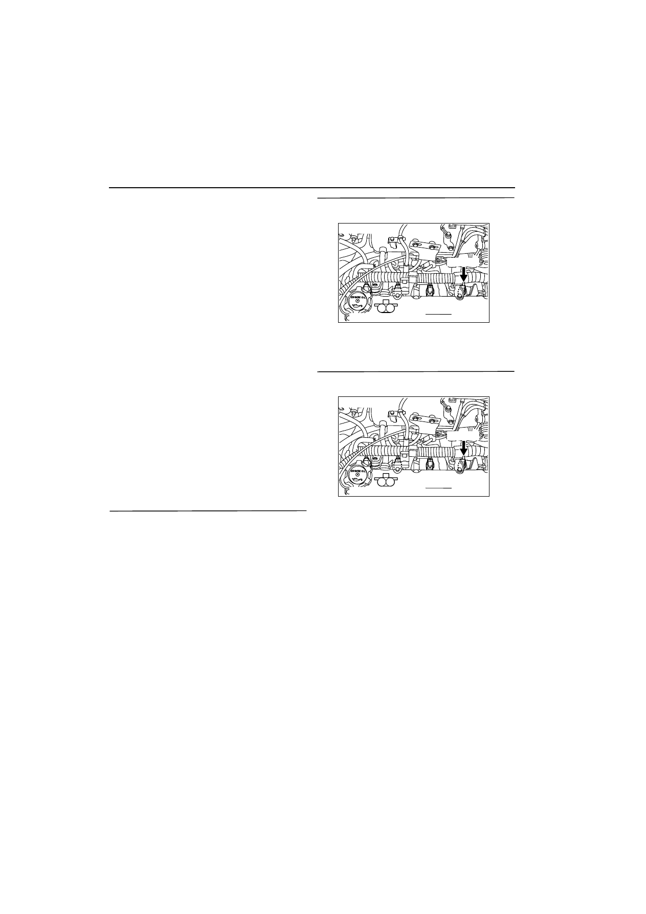
STEP 2. Connector check: B-05 No. 4 injector 
connector

Q: Is the check result normal?

YES : 

Go to Step 3 .

NO : 

Repair.

STEP 3. Measure resistance at B-05 No. 4 injector 
connector.

œ

Disconnect connector, and measure at injector 
side.

œ

Resistance between terminal No. 1 and No. 2.

OK: 10.5 

-

 13.5 

W

Q: Is the check result normal? 

YES : 

Go to Step 4 .

NO : 

Replace No. 4 injector.

AK300265

M

1

2

Harness side connector

Connector: B-05

AF

B-05 (GR)

AK300265

M

1

2

Harness side connector

Connector: B-05

AF

B-05 (GR)

TROUBLESHOOTING

MULTIPORT FUEL INJECTION (MFI)

13A-104

STEP 4. Measure voltage at B-05 No. 4 injector 
connector.

œ

Disconnect connector, and measure at harness 
side.

œ

Ignition switch: ON 

œ

Voltage between terminal No. 1 and earth.

OK: System voltage

Q: Is the check result normal?

YES : 

Go to Step 6 .

NO : 

Go to Step 5 .

STEP 5. Connector check: B-17X engine control 
relay connector

Q: Is the check result normal? 

YES : 

Check and repair harness between B-17X 

(terminal No. 1) engine control relay 
connector and B-05 (terminal No. 1) No. 4 
injector connector.

œ

Check power supply line for 
open/short circuit and damage.

NO : 

Repair.

STEP 6. Connector check: B-17X engine control 
relay connector

Q: Is the check result normal? 

YES : 

Go to Step 7.

NO : 

Repair.

AK300265

M

1

2

Harness side connector

Connector: B-05

AF

B-05 (GR)

AK300255

2

1

3

4

Relay box’s
triangle marks

AB

CONNECTOR: B-17X

B-17X

Harness side
connector

AK300265

M

1

2

Harness side connector

Connector: B-05

AF

B-05 (GR)

AK300255

2

1

3

4

Relay box’s
triangle marks

AB

CONNECTOR: B-17X

B-17X

Harness side
connector

TROUBLESHOOTING

MULTIPORT FUEL INJECTION (MFI)

13A-105

STEP 7. Check harness between B-17X (terminal 
No. 1) engine control relay connector and B-05 
(terminal No. 1) No. 4 injector connector.

œ

Check power supply line for damage.

Q: Is the check result normal?

YES : 

Go to Step 8 .

NO : 

Repair.

STEP 8. Connector check: C-134 engine-ECU 
connector

Q: Is the check result normal?

YES : 

Go to Step 9 .

NO : 

Repair.

STEP 9. Check harness between B-05 (terminal 
No. 2) No. 4 injector connector and C-134 
(terminal No. 15) engine-ECU connector.

œ

Check output line for open/short circuit and dam-
age.

Q: Is the check result normal? 

YES : 

Go to Step 10 .

NO : 

Repair.

AK300255

2

1

3

4

Relay box’s
triangle marks

AB

CONNECTOR: B-17X

B-17X

Harness side
connector

AK300265

M

1

2

Harness side connector

Connector: B-05

AF

B-05 (GR)

AK300257

1

14

4

19

5

22

6

17

8

15

9

18

7

20

16

2

13 12

23

24

25

26

21

3

10

11

AB

CONNECTOR: C-134

C-134

Harness side connector

AK300265

M

1

2

Harness side connector

Connector: B-05

AF

B-05 (GR)

AK300257

1

14

4

19

5

22

6

17

8

15

9

18

7

20

16

2

13 12

23

24

25

26

21

3

10

11

AB

CONNECTOR: C-134

C-134

Harness side connector

TROUBLESHOOTING

MULTIPORT FUEL INJECTION (MFI)

13A-106

STEP 10. Measure signal waveform at C-134 
engine-ECU connector (Use oscilloscope).

œ

Engine: Idling

œ

Transmission: Neutral

œ

Voltage between terminal No. 2 and earth.

OK: Waveform should be display on Inspec-
tion procedure using an oscilloscope (Refer 
to 

3

13A


).

Q: Is the check result normal? 

YES : 

Intermittent malfunction (Refer to GROUP 

00 

-

 How to Use 

Troubleshooting/Inspection Service Points 

3

00


).

NO : 

Replace engine-ECU.

Code No. P0300: Random cylinder mis-fire detected

OPERATION

œ

Refer to P0201 injector circuit 

3

13A


.

œ

Refer to P0202 injector circuit 

3

13A


.

œ

Refer to P0203 injector circuit 

3

13A


.

œ

Refer to P0204 injector circuit 

3

13A


.

FUNCTION

œ

If a misfire occurs while the engine is running, the 
engine speed changes for an instant.

œ

The engine-ECU checks for such changes in 
engine speed.

TROUBLE JUDGMENT

Check Conditions

œ

5 seconds later after the engine has started up.

œ

The engine speed is 500 

-

 4,500 r/min.

œ

The engine coolant temperature is 

-

10

•

C or 

higher.

œ

The intake air temperature is 

-

10

•

C or higher.

œ

The barometric pressure is 72 kPa or more.

œ

The volumetric efficiency is 30 

-

 60%.

œ

The adaptive learning has been completed with 
the vane that generates the crankshaft position 
signals.

œ

During the engine operation except the shift 
change or low speed driving and rapid accelera-
tion and deceleration, also intermittent operation 
of air compressor (A/C: within the 3 seconds after 
changing to ON from OFF or to OFF from ON).

œ

The throttle deviation is within the range of 

-

0.059 V/10ms to 0.059 V/10ms.

Judgment Criteria

œ

The number of misfiring (in the catalyst tempera-
ture of above 950

•

C) is beyond the specified 

number (of 7.3 % on more than the two cylinders) 
with the engine speed of 200 r/min.

Or

AK300257

1

14

4

19

5

22

6

17

8

15

9

18

7

20

16

2

13 12

23

24

25

26

21

3

10

11

AB

CONNECTOR: C-134

C-134

Harness side connector


Content   ..  58  59  60  61   ..