Mitsubishi Outlander (2003+). Manual - part 57


  Index      Mitsubishi     Mitsubishi Outlander - service repair manual 2003 year


Search            


Content   ..  55  56  57  58   ..


Mitsubishi Outlander (2003+). Manual - part 57


TROUBLESHOOTING

MULTIPORT FUEL INJECTION (MFI)

13A-91

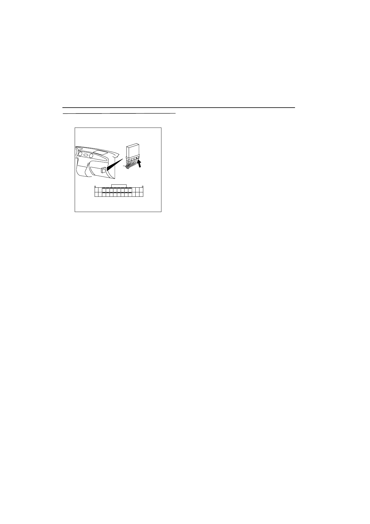
STEP 10. Measure signal waveform at C-134 
engine-ECU connector (Use oscilloscope).

œ

Engine: Idling

œ

Transmission: Neutral

œ

Voltage between terminal No. 1 and earth.

OK: Waveforms should be display on 
Inspection procedure using an oscilloscope 
(Refer to 

3

13A


).

Q: Is the check result normal?

YES : 

Intermittent malfunction (Refer to GROUP 

00 

-

 How to Use 

Troubleshooting/Inspection Service Points 

3

00


).

NO : 

Replace engine-ECU.

AK300257

1

14

4

19

5

22

6

17

8

15

9

18

7

20

16

2

13 12

23

24

25

26

21

3

10

11

AB

CONNECTOR: C-134

C-134

Harness side connector

TROUBLESHOOTING

MULTIPORT FUEL INJECTION (MFI)

13A-92

Code No. P0202: No. 2 Injector System

AK300272

2

1

2

1

2

1

2

1

1

2

3

4

1

14

4

19

5

22

6

17

8

15

9

18

7

20

16

2

13

12

23 24 25 26

21

3

10 11

AB

B-17X

Engine control relay

Injector 
No. 1

Injector 
No. 2

Injector 
No. 3

Injector 
No. 4

B-01

B-02

B-04

B-05

1

1

1

1

1

2

Y

Y-R

Y-G

L

2

2

2

2

Engine-ECU

1

14

2

15

Injector circuit

Battery

4

W-B

W-B

R

R

R

R

R

3

Wire colour code
B: Black  LG: Light green  G: Green  L: Blue  W: White  Y: Yellow  SB: Sky blue  BR: Brown  O: Orange  GR: Gray
R: Red  P: Pink  V:Violet

C-134

TROUBLESHOOTING

MULTIPORT FUEL INJECTION (MFI)

13A-93

OPERATION

œ

Power is supplied to the injector (terminal No. 1) 
from the engine control relay (terminal No. 1).

œ

The engine-ECU (terminal No. 14) makes the 
power transistor in the unit be in "ON" position, 
and that makes currents go on the injector (termi-
nal No. 2).

FUNCTION

œ

The engine-ECU controls the power supply inter-
val of the injector.

œ

The fuel injection amount of the injector depends 
on the power supply interval.

TROUBLE JUDGMENT

Check Conditions

œ

The engine speed is 50 

-

 1,000 r/mim.

œ

The throttle position sensor output voltage 1.15 V 
or less.

œ

Injector not in forced drive (actuator test) mode

Judgment Criteria

œ

No surge voltage of the injector coil is detected 
for 2 seconds.

PROBABLE CAUSE

œ

Failed No. 2 injector

œ

Open/short circuit in No. 2 injector circuit or loose 
connector contact

œ

Failed engine-ECU 

DIAGNOSIS PROCEDURE

STEP 1. MUT-II actuator test

œ

Refer to Actuator test reference table list 

3

13A


.

a. Item 02: No. 2 injector

OK: Idling state varies.

Q: Is the check result normal? 

YES : 

Intermittent malfunction (Refer to GROUP 

00 

-

 How to Use 

Troubleshooting/Inspection Service Points 

3

00


).

NO : 

Go to Step 2 .

STEP 2. Connector check: B-02 No. 2 injector 
connector

Q: Is the check result normal? 

YES : 

Go to Step 3 .

NO : 

Repair.

STEP 3. Measure at resistance B-02 No. 2 injector 
connector.

œ

Disconnect connector, and measure at injector 
side.

œ

Resistance between terminal No. 1 and No. 2.

OK: 10.5 

-

 13.5 

W

Q: Is the check result normal? 

YES : 

Go to Step 4 .

NO : 

Replace No. 2 injector.

AK300265

M

1

2

Harness side connector

Connector: B-02

B-02 (GR)

AD

B-02 (GR)

AK300265

M

1

2

Harness side connector

Connector: B-02

B-02 (GR)

AD

B-02 (GR)

TROUBLESHOOTING

MULTIPORT FUEL INJECTION (MFI)

13A-94

STEP 4. Measure voltage at B-02 No. 2 injector 
connector.

œ

Disconnect connector, and measure at harness 
side.

œ

Ignition switch: ON 

œ

Voltage between terminal No. 1 and earth.

OK: System voltage

Q: Is the check result normal? 

YES : 

Go to Step 6 .

NO : 

Go to Step 5 .

STEP 5. Connector check: B-17X engine control 
relay connector

Q: Is the check result normal? 

YES : 

Check and repair harness between B-17X 

(terminal No. 1) engine control relay 
connector and B-02 (terminal No. 1) No. 2 
injector connector.

œ

Check power supply line for 
open/short circuit and damage.

NO : 

Repair.

STEP 6. Connector check: B-17X engine control 
relay connector

Q: Is the check result normal? 

YES : 

Go to Step 7 .

NO : 

Repair.

AK300265

M

1

2

Harness side connector

Connector: B-02

B-02 (GR)

AD

B-02 (GR)

AK300255

2

1

3

4

Relay box’s
triangle marks

AB

CONNECTOR: B-17X

B-17X

Harness side
connector

AK300265

M

1

2

Harness side connector

Connector: B-02

B-02 (GR)

AD

B-02 (GR)

AK300255

2

1

3

4

Relay box’s
triangle marks

AB

CONNECTOR: B-17X

B-17X

Harness side
connector


Content   ..  55  56  57  58   ..