Mitsubishi Outlander (2003+). Manual - part 42


  Index      Mitsubishi     Mitsubishi Outlander - service repair manual 2003 year


Search            


Content   ..  40  41  42  43   ..


Mitsubishi Outlander (2003+). Manual - part 42


TROUBLESHOOTING

MULTIPORT FUEL INJECTION (MFI)

13A-31

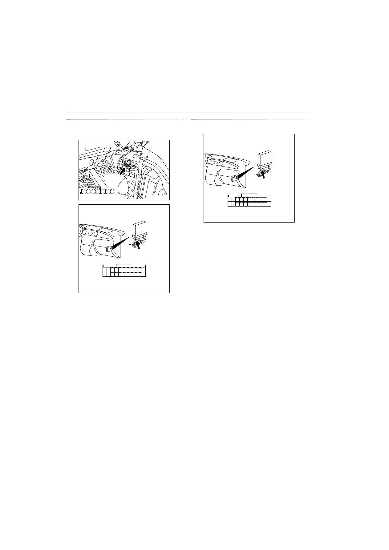
STEP 18. Check harness between B-08 (terminal 
No. 2) air flow sensor connector and C-137 
(terminal No. 85) engine-ECU connector.

œ

Check output line for short circuit and damage.

Q: Is the check result normal?

YES : 

Replace air flow sensor.

NO : 

Repair.

STEP 19. Measure voltage at C-137 engine-ECU 
connector.

œ

Measure engine-ECU terminal voltage.

œ

Ignition switch: ON

œ

Voltage between terminal No. 85 and earth.

OK:

Altitude 0m: 3.8 

-

 4.2 V 

Altitude 600m: 3.5 

-

 3.9 V

Altitude 1,200m: 3.3 

-

 3.7 V 

Altitude 1,800m: 3.0 

-

 3.4 V 

Q: Is the check result normal?

YES : 

Go to Step 21 . 

NO : 

Go to Step 20 . 

AK300253

3

4

5

1

2

6

7

AB

Harness side connector

B-08 (B)

Connector: B-08

AK300254

82

78

8180

89

90

91

92

79

87

71

74 73 72

76 75

77

85

88

83

84

86

AB

CONNECTOR: C-137

C-137

Harness side connector

AK300254

82

78

8180

89

90

91

92

79

87

71

74 73 72

76 75

77

85

88

83

84

86

AB

CONNECTOR: C-137

C-137

Harness side connector

TROUBLESHOOTING

MULTIPORT FUEL INJECTION (MFI)

13A-32

STEP 20. Connector check: C-137 engine-ECU 
connector

Q: Is the check result normal?

YES : 

Check and repair harness between B-08 

(terminal No. 2) air flow sensor connector 
and C-137 (terminal No. 85) engine-ECU 
connector.

œ

Check output line for open circuit and 
damage.

NO : 

Repair.

STEP 21. Connector check: C-137 engine-ECU 
connector

Q: Is the check result normal?

YES : 

Go to Step 8 . 

NO : 

Repair.

AK300254

82

78

8180

89

90

91

92

79

87

71

74 73 72

76 75

77

85

88

83

84

86

AB

CONNECTOR: C-137

C-137

Harness side connector

AK300253

3

4

5

1

2

6

7

AB

Harness side connector

B-08 (B)

Connector: B-08

AK300254

82

78

8180

89

90

91

92

79

87

71

74 73 72

76 75

77

85

88

83

84

86

AB

CONNECTOR: C-137

C-137

Harness side connector

TROUBLESHOOTING

MULTIPORT FUEL INJECTION (MFI)

13A-33

Code No. P0110: Intake Air Temperature Sensor System

OPERATION

œ

A power voltage of 5 V is applied to the intake air 
temperature sensor output terminal (terminal No. 
6) of the air flow sensor connector from the 
engine-ECU (terminal No. 72)

œ

The power voltage is earthed to the engine-ECU 
(terminal No. 40) from the air flow sensor (termi-
nal No. 5).

FUNCTION

œ

The intake air temperature sensor converts the 
intake air temperature into a voltage and inputs 
the voltage signal to the engine-ECU.

œ

In response to the signal, the engine-ECU cor-
rects the fuel injection amount, etc.

œ

The intake air temperature sensor is a kind of 
resistor, which has characteristics to reduce its 
resistance as the intake air temperature rises. 
Therefore, the sensor output voltage varies with 
the intake air temperature, and becomes lower as 
the intake air temperature rises.

TROUBLE JUDGMENT

Check Condition

œ

2 seconds later after the ignition switch has been 
in "ON" position or the engine has started up.

Judgment Criterion

œ

The sensor output voltage is 4.6 V or more 
(intake air temperature of below 

-

45

•

C or equiva-

lent) for 2 seconds.

Or

œ

The sensor output voltage is 0.2 V or loss (intake 
air temperature above 125

•

C or equivalent) for 2 

seconds.

PROBABLE CAUSE

œ

Failed intake air temperature sensor

œ

Open/short circuit in intake air temperature sen-
sor circuit or loose connector contact

œ

Failed engine-ECU

AK300259

2 3

7

4 5 6

1

34

33

32

36

35

37

42

45

31

39

38

46

40 41

43 44

82

78

81

80

89 90 9192

79

87

71

74

73

72

76

75

77

85

88

83 84

86

AB

40

72

B-08

Engine-ECU

5

6

Intake air temperature sensor circuit

20

17

J/C (1) 
C-16

B-W

B-W

Y-L

Wire colour code
B: Black  LG: Light green  G: Green  L: Blue  W: White  Y: Yellow  SB: Sky blue  BR: Brown  O: Orange  GR: Gray
R: Red  P: Pink  V:Violet

Intake air temperature sensor 
(Incorporated in air flow sensor)

C-137

C-135

5V

TROUBLESHOOTING

MULTIPORT FUEL INJECTION (MFI)

13A-34

DIAGNOSIS PROCEDURE

STEP 1. MUT-II data list

œ

Refer to Data list reference table 

3

13A


.

a. Item 13: Intake air temperature sensor

OK: At ambient temperature (atmospheric 
temperature) or equivalent.

Q: Is the check result normal?

YES : 

Intermittent malfunction (Refer to GROUP 

00 

-

 How to Use 

Troubleshooting/Inspection Service Points 

3

00


).

NO : 

Go to Step 2 .

STEP 2. Connector check: B-08 air flow sensor 
connector

Q: Is the check result normal?

YES : 

Go to Step 3 .

NO : 

Repair.

STEP 3. Check intake air temperature sensor 
itself.

œ

Check intake air temperature sensor itself (Refer 
to 

3

13A


).

Q: Is the check result normal?

YES : 

Go to Step 4 .

NO : 

Replace air flow sensor.

STEP 4. Measure voltage at B-08 air flow sensor 
connector.

œ

Disconnect connector, and measure at harness 
side.

œ

Voltage between terminal No. 5 and earth.

OK: 2 

W

 or less

Q: Is the check result normal?

YES : 

Go to Step 8 .

NO : 

Go to Step 5 .

STEP 5. Connector check: C-135 engine-ECU 
connector

Q: Is the check result normal?

YES : 

Go to Step 6 .

NO : 

Repair.

AK300253

3

4

5

1

2

6

7

AB

Harness side connector

B-08 (B)

Connector: B-08

AK300253

3

4

5

1

2

6

7

AB

Harness side connector

B-08 (B)

Connector: B-08

AK300256

34 33 32

36 35

37

42

45

31

39

38

46

40

41

43

44

AB

CONNECTOR: C-135

C-135

Harness side connector


Content   ..  40  41  42  43   ..