Mitsubishi Outlander (2003+). Manual - part 39


  Index      Mitsubishi     Mitsubishi Outlander - service repair manual 2003 year


Search            


Content   ..  37  38  39  40   ..


Mitsubishi Outlander (2003+). Manual - part 39


TROUBLESHOOTING

MULTIPORT FUEL INJECTION (MFI)

13A-19

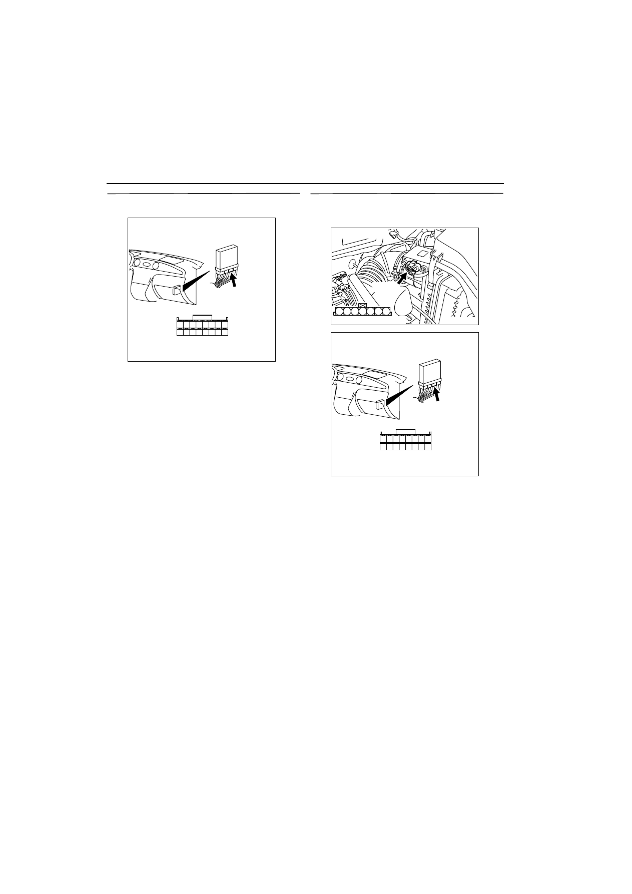
STEP 12. Connector check: C-135 engine-ECU 
connector

Q: Is the check result normal?

YES : 

Go to Step 13 .

NO : 

Repair.

STEP 13. Check harness between B-08 (terminal 
No. 5) air flow sensor connector and C-135 
(terminal No. 40) engine-ECU connector.

NOTE: Before checking harness, check intermediate 
connector C-16, and repair if necessary.

œ

Check earthing line for open circuit and damage.

Q: Is the check result normal?

YES : 

Go to Step 8 .

NO : 

Repair.

AK300256

34 33 32

36 35

37

42

45

31

39

38

46

40

41

43

44

AB

CONNECTOR: C-135

C-135

Harness side connector

AK300253

3

4

5

1

2

6

7

AB

Harness side connector

B-08 (B)

Connector: B-08

AK300256

34 33 32

36 35

37

42

45

31

39

38

46

40

41

43

44

AB

CONNECTOR: C-135

C-135

Harness side connector

TROUBLESHOOTING

MULTIPORT FUEL INJECTION (MFI)

13A-20

STEP 14. Measure voltage at B-08 air flow sensor 
connector.

œ

Use special tool test harness (MB991709) to con-
nect connector, and measure at pick-up harness.

œ

Ignition switch: ON

œ

Voltage between terminal No. 7 and earth.

OK: 7 

-

 8 V

Q: Is the check result normal?

YES : 

Go to Step 17 .

NO : 

Go to Step 15 .

STEP 15. Connector check: C-134 engine-ECU 
connector

Q: Is the check result normal?

YES : 

Go to Step 16 .

NO : 

Repair.

STEP 16. Check harness between B-08 (terminal 
No. 7) air flow sensor connector and C-134 
(terminal No. 19) engine-ECU connector.

œ

Check reset signal line for short circuit.

Q: Is the check result normal?

YES : 

Replace air flow sensor.

NO : 

Repair.

AK300253

3

4

5

1

2

6

7

AB

Harness side connector

B-08 (B)

Connector: B-08

AK300257

1

14

4

19

5

22

6

17

8

15

9

18

7

20

16

2

13 12

23

24

25

26

21

3

10

11

AB

CONNECTOR: C-134

C-134

Harness side connector

AK300253

3

4

5

1

2

6

7

AB

Harness side connector

B-08 (B)

Connector: B-08

AK300257

1

14

4

19

5

22

6

17

8

15

9

18

7

20

16

2

13 12

23

24

25

26

21

3

10

11

AB

CONNECTOR: C-134

C-134

Harness side connector

TROUBLESHOOTING

MULTIPORT FUEL INJECTION (MFI)

13A-21

STEP 17. Measure voltage at B-08 air flow sensor 
connector.

œ

Use special tool test harness (MB991709) to con-
nect connector, and measure at pick-up harness.

œ

Transmission: Neutral

œ

Voltage between terminal No. 7 and earth.

OK:

-

 1 V (Engine: Idling)

-

 9 V (Engine: 3,000 r/min)

Q: Is the check result normal?

YES : 

Go to Step 20 .

NO : 

Go to Step 18 .

STEP 18. Connector check: C-134 engine-ECU 
connector

Q: Is the check result normal?

YES : 

Go to Step 19 .

NO : 

Repair.

STEP 19. Check harness between B-08 (terminal 
No. 7) air flow sensor connector and C-134 
(terminal No. 19) engine-ECU connector.

œ

Check reset signal line for open circuit and dam-
age.

Q: Is the check result normal?

YES : 

Go to Step 8 .

NO : 

Repair.

AK300253

3

4

5

1

2

6

7

AB

Harness side connector

B-08 (B)

Connector: B-08

AK300257

1

14

4

19

5

22

6

17

8

15

9

18

7

20

16

2

13 12

23

24

25

26

21

3

10

11

AB

CONNECTOR: C-134

C-134

Harness side connector

AK300253

3

4

5

1

2

6

7

AB

Harness side connector

B-08 (B)

Connector: B-08

AK300257

1

14

4

19

5

22

6

17

8

15

9

18

7

20

16

2

13 12

23

24

25

26

21

3

10

11

AB

CONNECTOR: C-134

C-134

Harness side connector

TROUBLESHOOTING

MULTIPORT FUEL INJECTION (MFI)

13A-22

STEP 20. Measure output waveform at B-08 air 
flow sensor connector (Use oscilloscope).

œ

Use special tool test harness (MB991709) to con-
nect connector, and measure at pick-up harness.

œ

Engine: Idling

œ

Transmission: Neutral

œ

Voltage between terminal No. 3 and earth.

OK: Waveforms should be displayed on 
inspection procedure using an oscilloscope 
(Refer to 

3

13A


) and noise should not be 

displayed in the waveform.

Q: Is the check result normal?

YES : 

Go to Step 8 .

NO : 

Go to Step 21 .

STEP 21. Replace air flow sensor.

œ

After replacing the air flow sensor, re-check the 
trouble symptoms.

Q: Is the check result normal?

YES : 

Go to Step 22 .

NO : 

Check end.

STEP 22. Connector check: B-17X engine control 
relay connector

Q: Is the check result normal?

YES : 

Go to Step 23 .

NO : 

Repair.

STEP 23. Check harness between B-08 (terminal 
No. 4) air flow sensor connector and B-17X 
(terminal No. 1) engine control relay connector.

œ

Check power supply line for damage.

Q: Is the check result normal? 

YES : 

Go to Step 24 .

NO : 

Repair.

STEP 24. Connector check: C-134 engine-ECU 
connector

Q: Is the check result normal?

YES : 

Go to Step 25 .

NO : 

Repair.

AK300253

3

4

5

1

2

6

7

AB

Harness side connector

B-08 (B)

Connector: B-08

AK300255

2

1

3

4

Relay box’s
triangle marks

AB

CONNECTOR: B-17X

B-17X

Harness side
connector

AK300253

3

4

5

1

2

6

7

AB

Harness side connector

B-08 (B)

Connector: B-08

AK300255

2

1

3

4

Relay box’s
triangle marks

AB

CONNECTOR: B-17X

B-17X

Harness side
connector

AK300257

1

14

4

19

5

22

6

17

8

15

9

18

7

20

16

2

13 12

23

24

25

26

21

3

10

11

AB

CONNECTOR: C-134

C-134

Harness side connector


Content   ..  37  38  39  40   ..