Mitsubishi Outlander (2003+). Manual - part 36
SPECIAL TOOLS
MULTIPORT FUEL INJECTION (MFI)
13A-7
MB991223
A: MB991219
B: MB991220
C: MB991221
D: MB991222
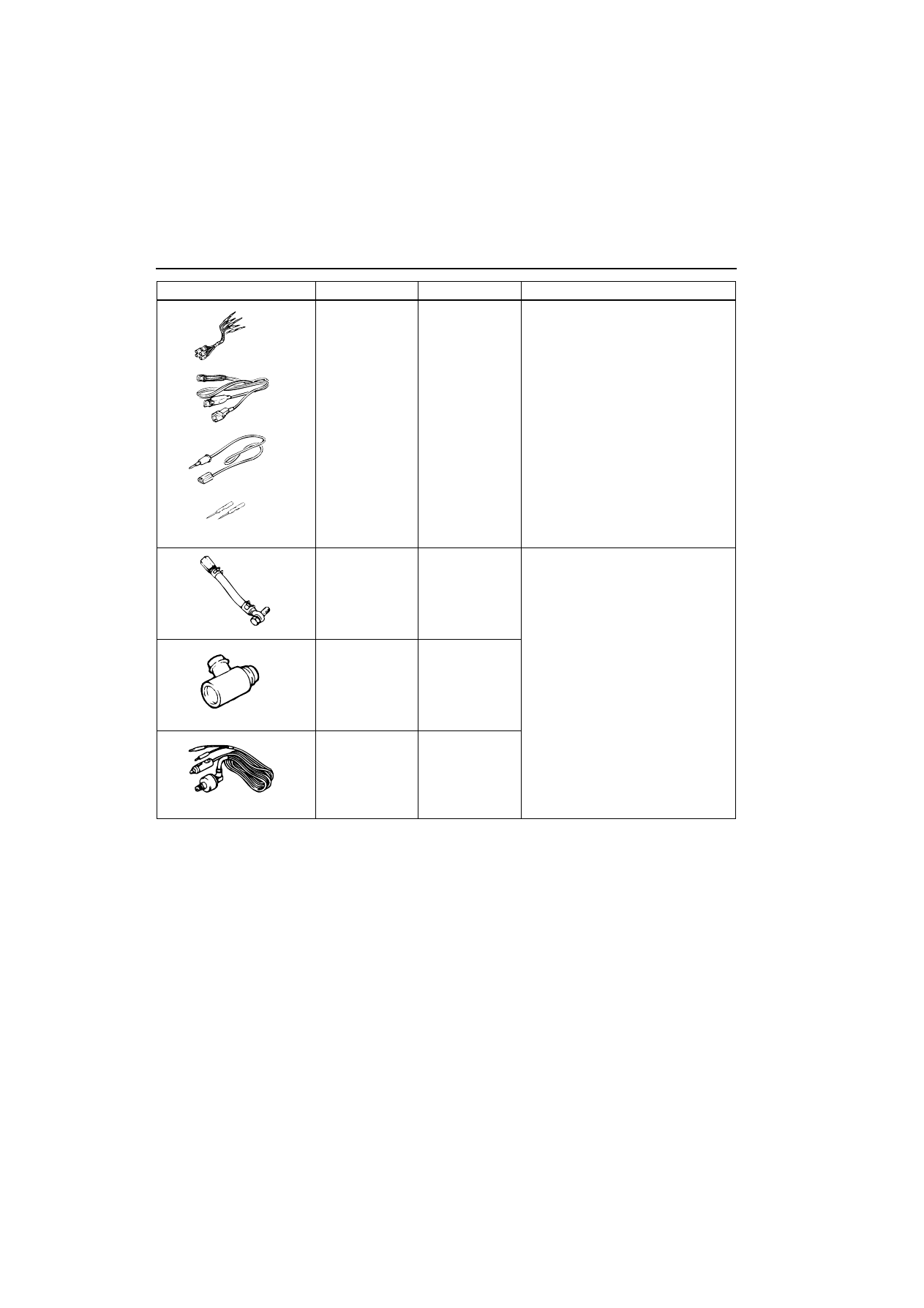
Harness set
A: Test harness
B: LED harness
C: LED harness
adapter
D: Probe
Check at the ECU terminals
A: Connector pin contact inspection
B: Power circuit inspection
C: Power circuit inspection
D: Commercial tester connection
MD998709
Adaptor hose
Measurement of fuel pressure
MD998742
Hose adaptor
MB991637
Fuel pressure
gauge set
Tool
Number
Name
Use
MB991223
MB991637