Mitsubishi Outlander (2003+). Manual - part 31
ENGINE ASSEMBLY
ENGINE MECHANICAL <4G69>
11C-51
AC308985
5.0 ± 1.0 N·m
5.0 ± 1.0 N·m
9.0 ± 2.0 N·m
9.0 ± 2.0 N·m
9.0 ± 2.0 N·m
1
5
4
3
2
AB
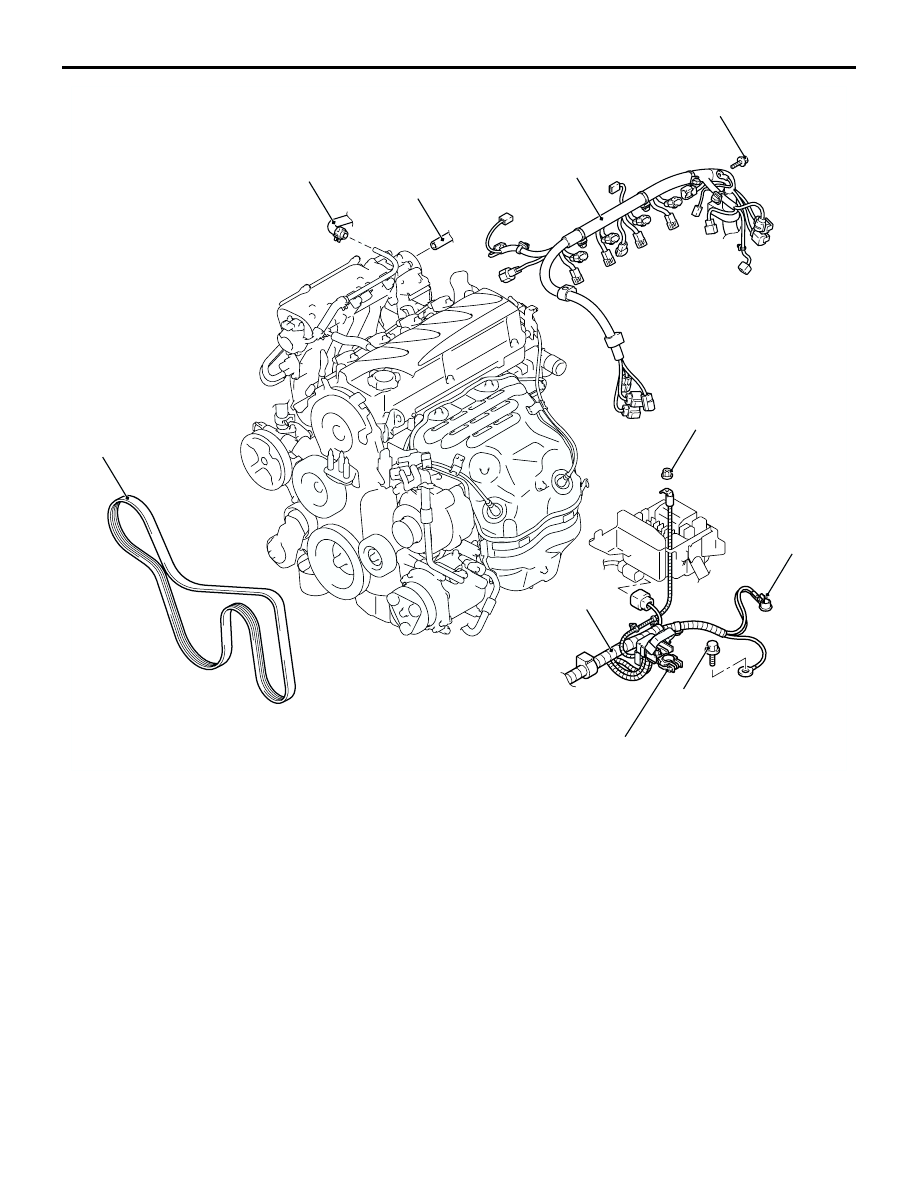
Removal steps
1.
Control wiring harness connection
2.
Battery wiring harness connection
3.
Canister vacuum hose connection
4.
Brake booster vacuum hose
connection
<<A>>
5.
Drive belt
Removal steps (Continued)