Mitsubishi Montero Sport (2004+). Manual - part 831


  Index      Mitsubishi     Mitsubishi Montero Sport - service repair manual 2004 year


Search            


Content   ..  829  830  831  832   ..


Mitsubishi Montero Sport (2004+). Manual - part 831


POWER STEERING HOSES

TSB Revision

STEERING

37A-47

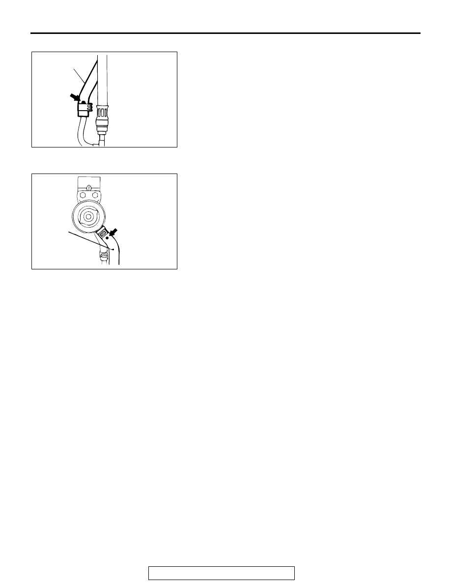
>>D<< RETURN HOSE INSTALLATION
Install the return hose so that the marking faces towards front 
of the vehicle.

.

>>E<< SUCTION HOSE INSTALLATION
Connect the suction hose so that the marking is positioned as 
shown in the illustration.

AC004445 AB

RETURN
HOSE

AC004446

SUCTION
HOSE

AB

STEERING LINKAGE

TSB Revision

STEERING

37A-48

STEERING LINKAGE

REMOVAL AND INSTALLATION

M1371003000079

Required Special Tool:

• MB991897: Ball Joint Remover

Post-installation Operation
• Checking Steering Wheel Position with Wheels Straight 

Ahead

• Front Wheel Alignment (Refer to GROUP 33A, On-vehicle 

Servic

P.33A-3

.)

• Press the dust cover with a finger to check whether the 

dust cover is cracked or damaged.

AC103639 AB

5

2

4

93 N·m
69 ft-lb

59 N·m
43  ft-lb

93 N·m
69 ft-lb

44 - 54 N·m
32 - 40 ft-lb

44 - 54 N·m
32 - 40 ft-lb

44 - 54 N·m
32 - 40 ft-lb

44 - 54 N·m
32 - 40 ft-lb

SEALANT: 
3M™ AAD PART NO. 8672, 8679, 8678, 8661, 8663 OR EQUIVALENT

2

3

1

1

1

1

1

1

5

2

N

N

N

N

N

N

SPECIFIED GREASE: 
MULTIPURPOSE GREASE SAE J310, NLGI No.2 OR EQUIVALENT

REMOVAL STEPS

1. COTTER PIN

<<A>> >>B<<

2. TIE ROD ASSEMBLY

<<A>> >>A<<

3. RELAY ROD
4. SELF-LOCKING NUT

<<A>>

5. IDLER ARM ASSEMBLY

STEERING LINKAGE

TSB Revision

STEERING

37A-49

REMOVAL SERVICE POINT

.

<<A>> TIE ROD ASSEMBLY/RELAY ROD/ IDLER ARM 
ASSEMBLY REMOVAL

CAUTION

• Do not remove the nut from ball joint. Loosen it and use 

special tool MB991897 to avoid possible damage to ball 
joint threads.

• Hang special tool MB991897 with cord to prevent it 

from falling. 

1. Install special tool MB991897 as shown in the figure.

2. Turn the bolt and knob as necessary to make the jaws of 

special tool MB991897 parallel, tighten the bolt by hand and 
confirm that the jaws are still parallel.
NOTE: When adjusting the jaws in parallel, make sure the 
knob is in the position shown in the figure.

3. Tighten the bolt with a wrench to disconnect the tie rod 

assembly, relay rod and idler arm assembly.

INSTALLATION SERVICE POINTS

.

>>A<< RELAY ROD AND BALL JOINT CONNECTION
Apply the specified grease to the top (lip) of the dust cover.

Specified grease: Multipurpose grease SAE J310, 
NLGI No.2 or equivalent

.

AC106820 AB

CORD

BOLT

MB991897

NUT

BALL JOINT

AC106821

KNOB

PARALLEL

BOLT

GOOD

BAD

AB

AC103636

STEERING LINKAGE

TSB Revision

STEERING

37A-50

>>B<< TIE ROD ASSEMBLY INSTALLATION

CAUTION

The outer end of the tie rod end has left thread.
1. Install the tie rod assembly so that the dimension is as 

shown in the illustration.
NOTE: The illustration at left shows the left side tie rod 
assembly. The right side tie rod assembly is symmetrical to 
the left side assembly.

2. Adjust the pipe so that the difference between dimensions 

(a) and (b) is 1.5 mm (0.059 inch) or less, and then 
temporarily tighten the lock nut.
NOTE: Fully tighten the lock nut after the tie rod assembly is 
installed to the body and the toe-in has been adjusted.

INSPECTION

M1371003100065

Check the rubber parts for cracks and break.

DUST COVER CHECK

1. Press the dust cover with a finger to check whether the dust 

cover is cracked or damaged.

2. If there are any cracks in or damage to the dust cover, 

replace the tie rod end assembly or idler arm.
NOTE: Cracked or damaged dust cover may cause damage 
to the ball joint. In addition, if the dust cover is damaged dur-
ing service work, replace the dust cover.

AC004448

FRONT

93˚-97˚

VIEW A

PIPE

TIE ROD END, 
OUTER

TIE ROD END, 
INNER

3.15 mm (12.0 in)

 A

AB

a

b


Content   ..  829  830  831  832   ..