Mitsubishi Montero Sport (2004+). Manual - part 799


  Index      Mitsubishi     Mitsubishi Montero Sport - service repair manual 2004 year


Search            


Content   ..  797  798  799  800   ..


Mitsubishi Montero Sport (2004+). Manual - part 799


GENERAL DESCRIPTION

TSB Revision

ANTI-LOCK BRAKING SYSTEM (ABS) <4WD>

35C-3

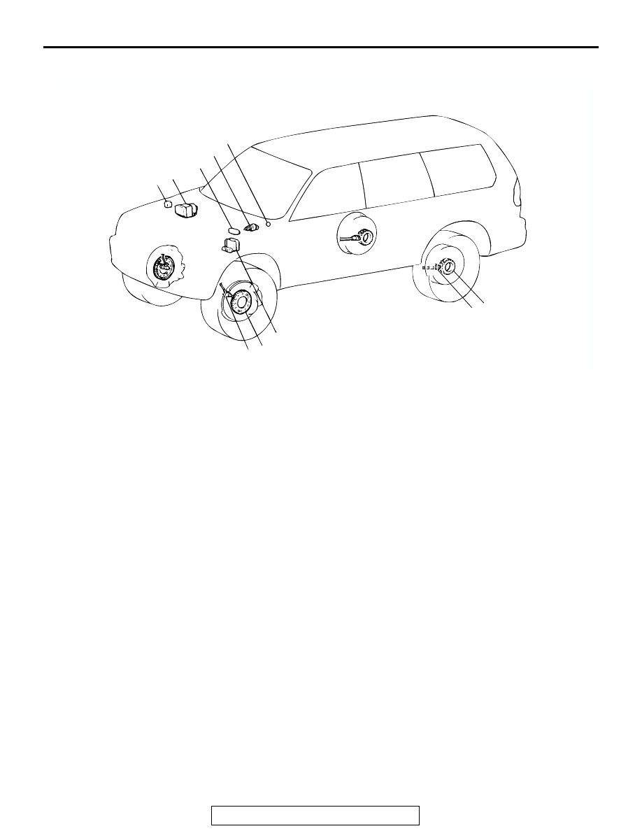
CONSTRUCTION DIAGRAM

AC309307 AB

6 5

7

5

6

1

2

3

4

8

1.

ABS WARNING LIGHT RELAY

2.

HYDRAULIC UNIT (INTEGRATED 
WITH ABS-ECU)

3.

DATA LINK CONNECTOR

4.

STOPLIGHT SWITCH

5.

ABS ROTOR

6.

WHEEL SPEED SENSOR

7.

ABS WARNING LIGHT

8.

G-SENSOR

ANTI-LOCK BRAKING SYSTEM (ABS) DIAGNOSIS

TSB Revision

ANTI-LOCK BRAKING SYSTEM (ABS) <4WD>

35C-4

ANTI-LOCK BRAKING SYSTEM (ABS) DIAGNOSIS

INTRODUCTION TO ANTI-LOCK BRAKING SYSTEM DIAGNOSIS

M1352012500426

The anti-lock braking system (ABS) operates differ-
ently from conventional brake systems. These differ-
ences include sounds, sensations, and vehicle 
performance that owners and service technicians 
who are not familiar with ABS may not be used to.
Some operational characteristics may seem to be 
malfunctions, but they are simply signs of normal 
ABS operation. When diagnosing the ABS system, 
keep these operational characteristics in mind. 
Inform the owner of the kind of performance charac-
teristics to expect from an ABS-equipped vehicle.

System Check Sound

When starting the engine, a thudding sound can 
sometimes be heard coming from the engine com-
partment. This is a normal sound during the ABS 
self-check.

ABS Operation Sounds and Sensations

During normal operation, the ABS makes several 
sounds that may seem unusual at first.

• A whining sound is caused by the ABS hydraulic 

unit motor.

• When pressure is applied to the brake pedal, the 

pulsation of the pedal causes a scraping sound.

• When the brakes are applied firmly, the ABS 

operates, rapidly applying and releasing the 
brakes many times per second. This repeated 
application and release of braking forces can 
cause the suspension to make a thumping sound 
and the tires to squeak.

Long Stopping Distances on Loose Road 
Surfaces

When braking on loose surfaces like snow-covered 
or gravel roads, the stopping distance can be longer 
for an ABS-equipped vehicle than the stopping dis-
tance for a vehicle with a conventional brake system.

Shock at Starting Check

Shock may be felt when the brake pedal is lightly 
pressed while driving at a low speed. This is a nor-
mal characteristic because the ABS system opera-
tion check is carried out when vehicle speed is 8 
km/h (5 mph) or less.

ABS Diagnostic Trouble Code Detection 
Conditions

ABS diagnostic trouble codes (ABS DTCs) are set 
under different conditions, depending on the mal-
function detected. Most ABS DTCs will only be set 
during vehicle operation. Some ABS DTCs will also 
be set during the ABS self-check immediately after 
the engine is started.
When you check if an ABS DTC will be displayed 
again after the DTC has been erased, you should 
recreate the ABS DTC set conditions. Depending on 
the detection timing and set conditions for the spe-
cific ABS DTC, you must either drive the vehicle or 
turn the engine off and restart it. To set the proper 
conditions for that DTC again, refer to "ABS DTC 
SET CONDITIONS" for each ABS DTC that you are 
trying to reset. 

ANTI-LOCK BRAKING SYSTEM (ABS) DIAGNOSIS

TSB Revision

ANTI-LOCK BRAKING SYSTEM (ABS) <4WD>

35C-5

TROUBLESHOOTING STRATEGY

M1352011100599

Use these steps to plan your diagnostic strategy. If 
you follow them carefully, you will be sure that you 
have exhausted most of the possible ways to find an 
ABS fault.
1. Gather information about the problem from the 

customer.

2. Verify that the condition described by the 

customer exists.

3. Check the vehicle for any ABS DTC.
4. If you cannot verify the condition and there are no 

ABS DTCs, the malfunction is intermittent. Refer 
to GROUP 00, How to use 
Troubleshooting/Inspection Service Points 

− How 

to Cope with Intermittent Malfunctions 

P.00-7

.

5. If you can verify the condition but there are no 

ABS DTCs, or the system cannot communicate 
with the scan tool, check that the basic brake 
system is operating properly.

• If the basic brake system is not operating prop-

erly, refer to the GROUP 35A, Basic Brake Sys-
tem Diagnosis 

P.35A-3

.

• If the basic brake system is operating properly, 

refer to 

P.35C-50

.

6. If there is an ABS DTC, record the number of the 

DTC, then erase the DTC from the memory using 
the scan tool.

7. Duplicate the ABS DTC set conditions to see if the 

same ABS DTC will set again.

• If the same ABS DTC sets again, perform the 

diagnostic procedures for the DTC. Refer to 

P.35C-11

.

• If you cannot get the same ABS DTC to set 

again, the malfunction is intermittent. Refer to 
GROUP 00, How to use How to Cope with Inter-
mittent Malfunctions 

P.00-7

.

DIAGNOSTIC FUNCTION

M1352011200745

HOW TO CONNECT THE SCAN TOOL (MUT-III)

Required Special Tools:

• MB991958: Scan Tool (MUT-III Sub Assembly)

• MB991824: Vehicle Communication Interface (V.C.I.)

• MB991827: MUT-III USB Cable

• MB991911: MUT-III Main Harness B

CAUTION

To prevent damage to scan tool MB991958, always turn the 
ignition switch to the "LOCK" (OFF) position before con-
necting or disconnecting scan tool MB991958.
1. Ensure that the ignition switch is at the "LOCK" (OFF) 

position.

2. Start up the personal computer.
3. Connect special tool MB991827 to special tool MB991824 

and the personal computer.

4. Connect special tool MB991911 to special tool MB991824.
5. Connect special tool MB991911 to the data link connector.
6. Turn the power switch of special tool MB991824 to the "ON" 

position.
NOTE: When the special tool MB991824 is energized, spe-
cial tool MB991824 indicator light will be illuminated in a 
green color.

7. Start the MUT-Ill system on the personal computer.

NOTE: Disconnecting the scan tool MB991958 is the 
reverse of the connecting sequence, making sure that the 
ignition switch is at the "LOCK" (OFF) position.

AK303629AB

MB991911

MB991827

MB991824 

16-PIN

ANTI-LOCK BRAKING SYSTEM (ABS) DIAGNOSIS

TSB Revision

ANTI-LOCK BRAKING SYSTEM (ABS) <4WD>

35C-6

HOW TO READ AND ERASE DIAGNOSTIC 
TROUBLE CODE WITH SCAN TOOL (MUT-III)

.

Required Special Tools:

• MB991958: Scan Tool (MUT-III Sub Assembly)

• MB991824: Vehicle Communication Interface (V.C.I.)

• MB991827: MUT-III USB Cable

• MB991911: MUT-III Main Harness B

CAUTION

To prevent damage to scan tool MB991958, always turn the 
ignition switch to the "LOCK" (OFF) position before con-
necting or disconnecting scan tool MB991958.
NOTE: If the battery voltage is low, diagnostic trouble codes will 
not be set. Check the battery if scan tool MB991958 does not 
display.
1. Connect scan tool MB991958 to the data link connector.
2. Turn the ignition switch to the "ON" position.
3. Select "Interactive Diagnosis" from the start-up screen.
4. Select "System select."
5. Choose "ABS" from the "CHASSIS" tab.
6. Select "MITSUBISHI."
7. Select "Diagnostic Trouble Code"
8. If a DTC is set, it is shown.
9. Choose "Erase DTCs" to erase the DTC.

AK303629AB

MB991911

MB991827

MB991824 

16-PIN


Content   ..  797  798  799  800   ..