Mitsubishi Montero Sport (2004+). Manual - part 764


  Index      Mitsubishi     Mitsubishi Montero Sport - service repair manual 2004 year


Search            


Content   ..  762  763  764  765   ..


Mitsubishi Montero Sport (2004+). Manual - part 764


LOWER ARM AND TORSION BAR

TSB Revision

FRONT SUSPENSION

33A-11

Required Special Tools:

• MB990833: Arbor

• MB990971: Base

• MB991897: Ball Joint Remover Puller

• MB991522: Torsion Bar Bushing Remover and 

Installer

REMOVAL SERVICE POINT

.

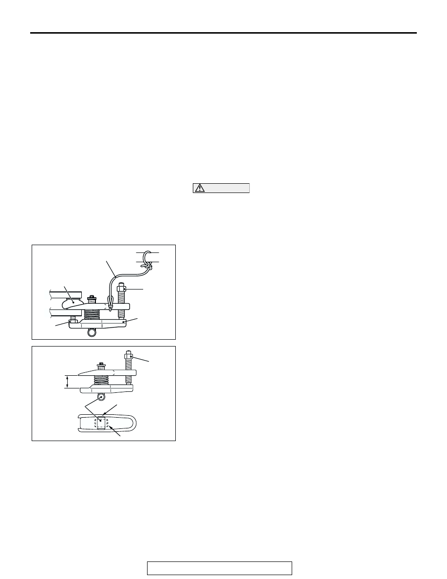
<<A>> LOWER ARM BALL JOINT DISCONNECTION

CAUTION

• Do not remove the nut from ball joint. Loosen it and use 

special tool MB991897 to avoid possible damage to ball 
joint threads.

• Hang special tool MB991897 with cord to prevent it 

from falling. 

1. Install the special tool MB991897 as shown in the figure.

2. Turn the bolt and knob as necessary to make the jaws of 

special tool MB991897 parallel, tighten the bolt by hand and 
confirm that the jaws are still parallel.
NOTE: When adjusting the jaws in parallel, make sure the 
knob is in the position shown in the figure.

3. Tighten the bolt with a wrench to disconnect the tie lower 

arm ball joint.

7. DUST COVERS

<<A>>

8. LOWER ARM BALL JOINT 

CONNECTION

9. STABILIZER BAR CONNECTION
10. BUMP STOPPER
11. LOWER ARM SHAFT
12. FRONT ANCHOR ARM
13. LOWER ARM
14. LOWER ARM BALL JOINT 

ASSEMBLY

15. STOPPER BOLT

REMOVAL STEPS (Continued)

AC106820 AB

CORD

BOLT

MB991897

NUT

BALL JOINT

AC106821

KNOB

PARALLEL

BOLT

GOOD

BAD

AB

LOWER ARM AND TORSION BAR

TSB Revision

FRONT SUSPENSION

33A-12

INSTALLATION SERVICE POINTS

.

>>A<< TORSION BAR/REAR ANCHOR ARM INSTALLA-
TION
1. Check the identification marks at the end of the left and right 

torsion bars.

→ for right side

→ for left side

2. When installing the torsion bar, align the white mark on the 

serrated section of the torsion bar with the mating mark on 
the anchor arm.

3. Mount the anchor bolt as shown in the illustration, and install 

the rear anchor arm adjusting nut.

.

>>B<< BUMP STOPPER AND BUMP STOPPER BRACKET 
CLEARANCE ADJUSTMENT
1. With the vehicle in an unladen condition, dimension A from 

the bump stopper to the bump stopper bracket should be 18 
− 20 mm (0.71 − 0.79 inch).
NOTE: Dimension A will be 18 mm (0.71 inch) (B = 50 mm 
[2.0 inches]) when the bump stopper is a new part. When 
the bump stopper is worn and becomes less than 50 mm 
(2.0 inches), dimension A will increase by the decreased 
amount.

2. If dimension A is not 18 

− 20 mm (0.71 − 0.79 inch), adjust 

the anchor arm assembly adjusting nut.

AC005009 AB

MATING MARK

REAR ANCHOR
ARM ASSEMBLY

MATING MARK

IDENTIFICATION
MARK

MATING
MARK

MATING MARK

IDENTIFICATION
MARK

FRONT
ANCHOR
ARM

WHITE OR YELLOW
MARK

AC005010 AB

REAR ANCHOR ARM

ANCHOR BOLT

AC005001AB

A

B

BUMP STOPPER
BRACKET

BUMP STOPPER

LOWER ARM AND TORSION BAR

TSB Revision

FRONT SUSPENSION

33A-13

INSPECTION

M1332010800054

.

LOWER ARM BALL JOINT END PLAY
Check the lower arm ball joint assembly end play by following 
the steps below.
1. Measure the lower arm ball joint assembly end play with a 

dial indicator.

Limit: 0.3 mm (0.01 inch)

2. If the lower arm ball joint assembly end play exceeds the 

limit, replace the lower arm ball joint assembly.

.

LOWER ARM BALL JOINT DUST COVER CHECK
1. Press the dust cover with a finger to check whether the dust 

cover is cracked or damaged.

2. When dust cover is cracked or damaged, replace the lower 

arm ball joint assembly.
NOTE: If the dust cover is cracked, the ball joint could be 
damaged, so if the dust cover is damaged during mainte-
nance work, replace it.

REAR LOWER ARM BUSHING REPLACEMENT

M1332008100382

1. Using the special tool MB991522, remove the lower arm 

bushing (A) from the bracket.
NOTE: When removing the left hand rear lower arm bush-
ing, detach the differential carrier. (Refer to GROUP 26, Dif-
ferential carrie

P.26-40

.)

2. Using the special tool MB991522, press-fit the lower arm 

bushing (A) into the bracket.

AC005012 AB

AC005013 AB

MB991522

AC005014 AB

MB991522

LOWER ARM AND TORSION BAR

TSB Revision

FRONT SUSPENSION

33A-14

NOTE: Install the rear lower arm bushing in the direction 
shown in the illustration.

FRONT LOWER ARM BUSHING REPLACEMENT

M1332008100393

1. Remove the front lower arm bushing from the lower arm by 

using special tools MB990883, MB990971.

2. Coat the front lower arm bushing and the lower arm with 

soap solution and press-fit the front lower arm bushing into 
the lower arm by using special tools MB990883 and 
MB990971 and taking care not to twist or tilt the front lower 
arm bushing.
NOTE: Press-fit the front lower arm bushing again from the 
opposite side to equalize bushing projections at both ends.

LOWER ARM BALL JOINT DUST COVER 
REPLACEMENT

M1332008200293

Only when dust cover is damaged accidentally during service 
work, replace the dust cover as follows:
1. Apply multipurpose grease to the interior of the dust cover 

and the lower arm ball joint.

2. Secure the dust cover to the lower arm ball joint with ring.

AC005015 AD

FRONT OF VEHICLE

AC005016 AB

MB990883

MB990971

AC005017AB

MB990971

MB990883

AC005018 AB


Content   ..  762  763  764  765   ..