Mitsubishi Montero Sport (2004+). Manual - part 754


  Index      Mitsubishi     Mitsubishi Montero Sport - service repair manual 2004 year


Search            


Content   ..  752  753  754  755   ..


Mitsubishi Montero Sport (2004+). Manual - part 754


AIR BAG MODULES AND CLOCK SPRING

TSB Revision

SUPPLEMENTAL RESTRAINT SYSTEM (SRS)

52B-85

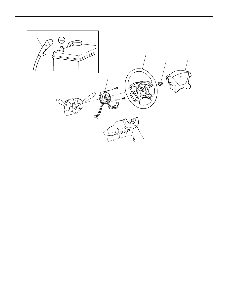
<Air bag module (driver's side), clock spring>

AC003312

1

5

3

39 N·m
29 ft-lb

2

4

AB

AIR BAG MODULE REMOVAL 
STEPS

<<A>>

1.

NEGATIVE (

−) BATTERY CABLE 

CONNECTION

<<B>>

2.

AIR BAG MODULE
CLOCK SPRING REMOVAL 
STEPS

<<A>>

1.

NEGATIVE (

−) BATTERY CABLE 

CONNECTION

<<B>>

2.

AIR BAG MODULE

<<C>>

3.

STEERING WHEEL

4.

COLUMN COVER LOWER

<<D>>

5.

CLOCK SPRING
AIR BAG MODULE 
INSTALLATION STEPS

>>A<<

PRE-INSTALLATION 
INSPECTION

>>D<<

2.

AIR BAG MODULE

1.

NEGATIVE (

−) BATTERY CABLE 

CONNECTION

>>E<<

POST-INSTALLATION 
INSPECTION
CLOCK SPRING 
INSTALLATION STEPS

>>A<<

PRE-INSTALLATION 
INSPECTION

>>B<<

5.

CLOCK SPRING

4.

COLUMN COVER LOWER

>>C<<

3.

STEERING WHEEL

>>D<<

2.

AIR BAG MODULE

1.

NEGATIVE (

−) BATTERY CABLE 

CONNECTION

>>E<<

POST-INSTALLATION 
INSPECTION

AIR BAG MODULE 
INSTALLATION STEPS 

AIR BAG MODULES AND CLOCK SPRING

TSB Revision

SUPPLEMENTAL RESTRAINT SYSTEM (SRS)

52B-86

<Air bag module (front passenger's side)>

Required Special Tools:

• MB991958: Scan Tool (MUT-III Sub Assembly)

• MB991824: Vehicle Communication Interface (V.C.I.)
• MB991827: MUT-III USB Cable
• MB991911: MUT-III Main Harness B

• MB990803: Steering Wheel Puller
• MB991613: SRS Check Harness

AC003313AB

1

3

2

AIR BAG MODULE REMOVAL 
STEPS

<<A>>

1.

NEGATIVE (

−) BATTERY CABLE 

CONNECTION

2.

STOPPER

<<E>>

3.

AIR BAG MODULE

AIR BAG MODULE 
INSTALLATION STEPS

>>A<<

PRE-INSTALLATION INSPECTION

3.

AIR BAG MODULE 

2.

STOPPER

1.

NEGATIVE (

−) BATTERY CABLE 

CONNECTION

>>E<<

POST-INSTALLATION 
INSPECTION

AIR BAG MODULES AND CLOCK SPRING

TSB Revision

SUPPLEMENTAL RESTRAINT SYSTEM (SRS)

52B-87

REMOVAL SERVICE POINTS

.

<<A>> NEGATIVE (

) BATTERY CABLE DISCONNECTION

DANGER

Wait at least 60 seconds after disconnecting the bat-
tery cable before doing any further work. (Refer to 

P.52B-17

.)

WARNING

Battery posts, terminals and related accessories con-
tain lead and lead compounds. WASH HANDS AFTER 
HANDLING.

Disconnect the negative (

−) battery cable from the battery and 

tape the terminal to prevent accidental connection and air bags 
deployment.

.

<<B>> AIR BAG MODULE REMOVAL (DRIVER'S SIDE) 
1. Remove the air bag module mounting screws (TORX

 

screws) at the sides of the steering wheel.
NOTE: Do not remove the screws from the holders.

CAUTION

When disconnecting the air bag module-to-clock spring 
connector, take care not to apply excessive force to it.

WARNING

The removed air bag module should be stored in a 
clean, dry place with the pad cover face up.

2. When disconnecting the connector of the clock spring from 

the air bag module, press the air bag's lock toward the outer 
side to spread it open. Use a flat-tipped screwdriver, as 
shown in the figure at the left, to pry gently to remove the 
connector.

.

<<C>> STEERING WHEEL REMOVAL

CAUTION

Do not hammer on the steering wheel. Doing so may dam-
age the collapsible column mechanism.

.

ACX00583

INSULATING TAPE

BATTERY

BATTERY CABLE (–)

AC

AC003314

SECTION A - A

A

A

MOUNTING SCREW
(TORX® SCREW)

AB

AC000396AB

FLAT-TIPPED
SCREWDRIVER

LOCK

CLOCK
SPRING-TO-AIR
BAG MODULE
CONNECTOR

LOCK

AC003315AB

MB990803

AIR BAG MODULES AND CLOCK SPRING

TSB Revision

SUPPLEMENTAL RESTRAINT SYSTEM (SRS)

52B-88

<<D>> CLOCK SPRING REMOVAL

WARNING

The removed clock spring should be stored in a 
clean, dry place.

.

<<E>> AIR BAG MODULE REMOVAL (FRONT 
PASSENGER'S SIDE)

WARNING

The removed air bag module should be stored in a 
clean, dry place with the ad cover face up.

INSTALLATION SERVICE POINTS

.

>>A<< PRE-INSTALLATION INSPECTION 

WARNING

Dispose of air bag modules only according to the 
specified procedure. (Refer to

P.52B-96

.) 

1. When installing the new air bag modules and clock spring, 

refer to "INSPECTION" (

P.52B-90

).

2. Connect the negative (

−) battery cable. 

CAUTION

To prevent damage to scan tool MB991958, always turn the 
ignition switch to the "LOCK"(OFF) position before con-
necting or disconnecting scan tool MB991958. 
3. Connect scan tool MB991958 to the data link connector. 
4. Turn the ignition key to the "ON" position. 
5. Conduct diagnostic test using scan tool MB991958 to 

ensure entire SRS operates properly. 

WARNING

Wait at least 60 seconds after disconnecting the bat-
tery cable before doing any further work. (Refer to 

P.52B-17

.)

6. Turn the ignition key to the "OFF" position. Disconnect the 

negative (

−) battery cable and tape the terminal to prevent 

accidental connection and air bags deployment. 

.

AK303629AB

MB991911

MB991827

MB991824 

16-PIN


Content   ..  752  753  754  755   ..