Mitsubishi Montero Sport (2004+). Manual - part 740


  Index      Mitsubishi     Mitsubishi Montero Sport - service repair manual 2004 year


Search            


Content   ..  738  739  740  741   ..


Mitsubishi Montero Sport (2004+). Manual - part 740


SRS AIR BAG DIAGNOSIS

TSB Revision

SUPPLEMENTAL RESTRAINT SYSTEM (SRS)

52B-29

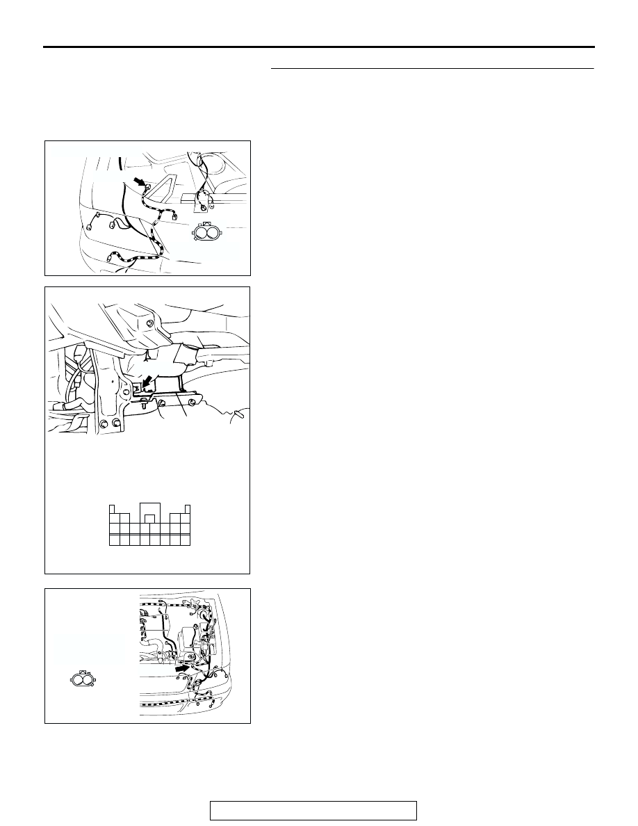
Step 3. Check the wiring harness between the right front 
impact sensor connector A-32 (terminals 1 and 2) and 
SRS-ECU connector C-24 (terminals 1 and 2) as well as 
between left front impact sensor connector A-20 (terminals 
1 and 2) and SRS-ECU connector C-24 (terminals 3 and 4).

AC003287AD

CONNECTOR: A-32

A-32 (Y)

2

1

HARNESS SIDE
(REAR VIEW)

AC202743

20

19

18

17

7

15

8

16

6

5

4

12

13 14

3

2

1

9 10 11

CONNECTOR: C-24

C-24 (Y)

C-24 HARNESS CONNECTOR:
HARNESS SIDE 
(REAR VIEW) 

AD

SRS-ECU

AC309461AC

CONNECTOR: A-20

A-20 (Y)

HARNESS SIDE
CONNECTOR
(FRONT VIEW)

2

1

SRS AIR BAG DIAGNOSIS

TSB Revision

SUPPLEMENTAL RESTRAINT SYSTEM (SRS)

52B-30

NOTE: After inspecting intermediate connectors C-17, inspect 
the wiring harness. If intermediate connectors are damaged, 
repair or replace them. Refer to GROUP 00E, Harness Con-
nector Inspection 

P.00E-2

. Then go to Step 4.

• Check the front impact sensor output line for open or 

short circuit.

Q: Is the check result satisfactory?

YES : Go to Step 4.
NO :  Repair the wiring harness.

Step 4. Recheck for diagnostic trouble code.

Check again if the DTC is set.
(1) Erase the DTC.
(2) Turn the ignition switch to the "ON" position.

(3) Check if the DTC is set.
(4) Turn the ignition switch to the "LOCK" (OFF) position.
Q: Is DTC 1A, 1B, 1C, 1D, 2A, 2B, 2C or 2D set?

YES : Replace the SRS-ECU (Refer to 

P.52B-82

).

NO :  The procedure is complete. (If no malfunctions are 

found in all steps, an intermittent malfunction is 
suspected. Refer to GROUP 00, How to Use 
Troubleshooting/Inspection Service Points 

− How to 

Cope with Intermittent Malfunction 

P.00-7

).

AC003286

CONNECTOR: C-17

AC

C-17

17

7

15

5

16

6

12 13

10

3

11

14

4

8

1

9

2

C-17

AK303629AB

MB991911

MB991827

MB991824 

16-PIN

SRS AIR BAG DIAGNOSIS

TSB Revision

SUPPLEMENTAL RESTRAINT SYSTEM (SRS)

52B-31

DTC 14: Analog G-sensor System in the SRS-ECU DTC 15: Safing G-Sensor Short Circuit DTC 16: 
Safing G-Sensor Open Circuit DTC 31: SRS-ECU Capacitor Circuit Voltage too High DTC 32: SRS-ECU 
Capacitor Circuit Voltage too Low DTC 45: SRS-ECU Non-Volatile Memory (EEPROM) and A/D 
Converter System DTC 51: Driver's Side Air Bag Module (Squib Ignition Drive Circuit) System 
Detected Short Circuit DTC 52: Driver's Side Air Bag Module (Squib Ignition Drive Circuit) System 
Detected Open Circuit DTC 54: Passenger (Front) Side Air Bag Module (Squib Ignition Drive Circuit) 
System Detected Short Circuit DTC 55: Passenger (Front) Side Air Bag Module (Squib Ignition Drive 
Circuit) System Detected Open Circuit DTC 56: Driver Side Seat Belt Pre-tensioner (Squib Ignition 
Drive Circuit) System Detected Short Circuit DTC 57: Driver Side Seat Belt Pre-tensioner (Squib 
Ignition Drive Circuit) System Detected Open Circuit

.

DTC SET CONDITIONS
These DTC's are set when a fault is detected in the 
SRS-ECU.

The most likely causes for the code to be set are 
shown in the table below:

.

.

TROUBLESHOOTING HINTS
Malfunction of the SRS-ECU 

DIAGNOSIS

Replace the SRS-ECU. Refer to 

P.52B-82

.

DTC

DEFECTIVE PART

SYMPTOMS

14

Analog G-sensor

• When the analog G-sensor is not operating 

• When the characteristics of the analog 

G-sensor are abnormal 

• When the output from the analog G-sensor is 

abnormal 

15

Safing G-sensor

• Short circuit in the safing G-sensor 

16

• Open circuit in the safing G-sensor 

31

Capacitor 

• Voltage at the capacitor terminal is higher 

than the specified value for 5 seconds or more 

32

• Voltage at the capacitor terminal is lower than 

the specified value for 5 seconds or more 
(This is not detected if DTC's No.41 or 42 
indicating battery voltage drop has been 
output.) 

45

Non-volatile memory (EEPROM) 
and A/D converter 

• When the non-volatile memory (EEPROM) 

and A/D converter system are abnormal

51

Driver's side air bag module 
(squib ignition drive circuit) 

• Short circuit in the squib ignition drive circuit

52

• Open circuit in the squib ignition drive circuit 

54

Front passenger's side air bag 
module (squib ignition drive 
circuit) 

• Short circuit in the squib ignition drive circuit

55

• Open circuit in the squib ignition drive circuit

56

Driver side seat belt pre-tensioner 
(squib ignition drive circuit) 

• Short circuit in the squib ignition drive circuit

57

• Open circuit in the squib ignition drive circuit

SRS AIR BAG DIAGNOSIS

TSB Revision

SUPPLEMENTAL RESTRAINT SYSTEM (SRS)

52B-32

DTC 21 : Driver's Side Air Bag Module (Squib) System Fault 1DTC 22: Driver's Side Air Bag Module 
(Squib) System Fault 2 DTC 61: Driver's Side Air Bag Module (Squib) System Fault for Power Supply 
Circuit DTC 62: Driver's Side Air Bag Module (Squib) System Fault for Ground circuit

Driver's Side Air Bag Module Squib Circuit

AC003288

CONNECTOR: C-24

AE

SRS-ECU

C-24 (Y)

AC003293

CONNECTORS: D-18, D-20

CLOCK
SPRING

D-20

D-18 (R)

AC


Content   ..  738  739  740  741   ..