Mitsubishi Montero Sport (2004+). Manual - part 620


  Index      Mitsubishi     Mitsubishi Montero Sport - service repair manual 2004 year


Search            


Content   ..  618  619  620  621   ..


Mitsubishi Montero Sport (2004+). Manual - part 620


AUTOMATIC TRANSMISSION DIAGNOSIS

TSB Revision

AUTOMATIC TRANSMISSION

23A-45

DTC SET CONDITIONS

Check Conditions

• Engine speed: 1,000 r/min or more.

• Output speed: 1,000 r/min or more.

• Accumulated time in above condition: 10 min-

utes.

Judgement Criteria

• Transmission fluid temperature sensor voltage: 

4.5 volts or more. (1 second)

.

OBD-II DRIVE CYCLE PATTERN
Start the engine, drive at 60 km/h (37 mph) or more 
for 15 minutes in total.

.

TROUBLESHOOTING HINTS (The most likely 
causes for this code to be set are:)

• Malfunction of the transmission fluid temperature 

sensor circuit

• Damaged harness, connector

• Malfunction of the PCM

DIAGNOSIS

Required Special Tool:

• MB991958: Scan Tool (MUT-III Sub Assembly)

• MB991824: V.C.I.

• MB991827: MUT-III USB Cable

• MB991911: MUT-III Main Harness B

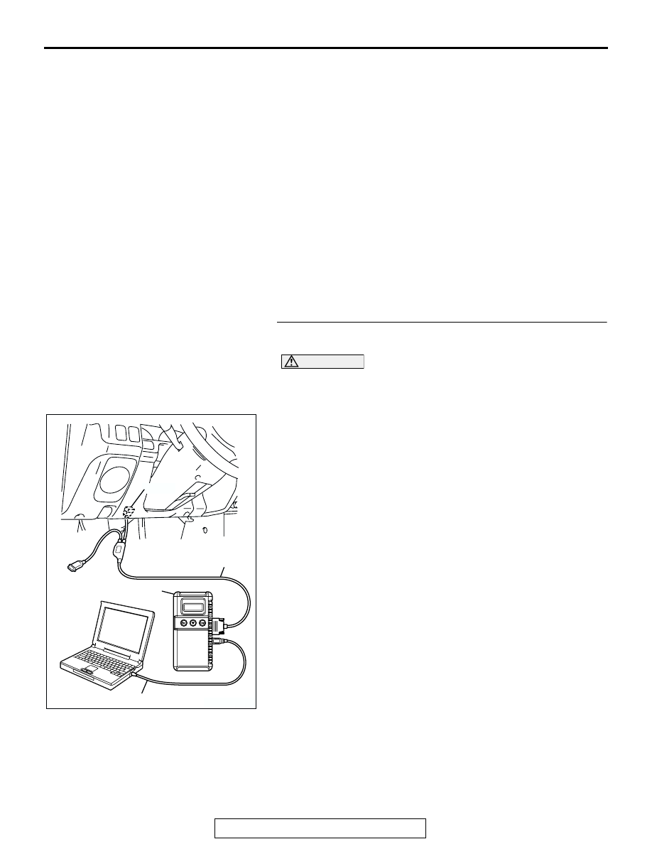
STEP 1. Using scan tool MB991958, check data list item 15: 
Transmission Fluid Temperature Sensor.

CAUTION

To prevent damage to scan tool MB991958, always turn the 
ignition switch to the "LOCK" (OFF) position before con-
necting or disconnecting scan tool MB991958.
(1) Connect scan tool MB991958 to the data link connector.
(2) Start the engine.
(3) Set scan tool MB991958 to data reading mode.

• Item 15: Transmission Fluid Temperature Sensor.

• When the engine is cool: Almost equal to the ambi-

ent temperature (atmospheric temperature).
NOTE: Set scan tool MB991958 to data reading 
mode for item number 13, Intake Air Temperature 
(IAT) Sensor and note the temperature measure-
ment. When the engine is cool, the temperature 
should be almost equal to the ambient temperature 
(atmospheric temperature), and the IAT sensor mea-
surement should be approximately the same as the 
Transmission Fluid Temperature Sensor.

• When the engine is warm: 70 to 80°C (158 to 176°F)

(4) Turn the ignition switch to "LOCK" (OFF) position.
Q: Is the sensor operating properly?

YES : It can be assumed that this malfunction is intermittent. 

Refer to GROUP 00, How to Use 
Troubleshooting/Inspection Service Points 

− How to 

Cope with Intermittent Malfunction 

P.00-7

.

NO :  Go to Step 2.

AK303629AB

MB991911

MB991827

MB991824 

16-PIN

AUTOMATIC TRANSMISSION DIAGNOSIS

TSB Revision

AUTOMATIC TRANSMISSION

23A-46

STEP 2. Measure the sensor output voltage at the A/T 
control solenoid valve assembly connector B-02 by 
backprobing.

(1) Do not disconnect connector B-02.
(2) Turn the ignition switch to the "ON" position.

(3) Measure the voltage between terminal 1 and ground by 

backprobing.

• When transmission fluid temperature is 20°C (68°F), 

voltage should measure between 3.8 and 4.0 volts.

• When transmission fluid temperature is 40°C (104°F), 

voltage should measure between 3.2 and 3.4 volts.

• When transmission fluid temperature is 80°C (176°F), 

voltage should measure between 1.7 and 1.9 volts.

(4) Turn the ignition switch to the "LOCK" (OFF) position.
Q: Is the measured voltage within the specified range?

YES : Go to Step 6.
NO :  Go to Step 3.

STEP 3. Measure the ground voltage at the A/T control 
solenoid valve assembly connector B-02 by backprobing.

(1) Do not disconnect connector B-02.
(2) Turn the ignition switch to the "ON" position.

(3) Measure the voltage between terminal 2 and ground by 

backprobing.

• The voltage should measure 0.5 volt or less.

(4) Turn the ignition switch to the "LOCK" (OFF) position.
Q: Is the measured voltage 0.5 volt or less?

YES : Go to Step 4.
NO :  Go to Step 7.

AC202314

6

10

4

9

5

3

8

2

7

1

CONNECTOR: B-02

TRANSMISSION
CONTROL CABLE

B-02 (B)

AB

5

2

1

7

3

8

4

9

6

10

AC200996AF

B-02 HARNESS
CONNECTOR: 
HARNESS SIDE

AC202314

6

10

4

9

5

3

8

2

7

1

CONNECTOR: B-02

TRANSMISSION
CONTROL CABLE

B-02 (B)

AB

5

2

1

7

3

8

4

9

6

10

AC201005AF

B-02 HARNESS
CONNECTOR: 
HARNESS SIDE

AUTOMATIC TRANSMISSION DIAGNOSIS

TSB Revision

AUTOMATIC TRANSMISSION

23A-47

STEP 4. Check the sensor output voltage at A/T control 
solenoid valve assembly connector B-02.

(1) Disconnect connector B-02 and measure at the harness 

side.

(2) Turn the ignition switch to the "ON" position.

(3) Measure the voltage between terminal 1 and ground.

• The voltage should measure between 4.5 and 4.9 volts.

(4) Turn the ignition switch to the "LOCK" (OFF) position.
Q: Is the measured voltage between 4.5 and 4.9 volts?

YES : Go to Step 5.
NO :  Go to Step 9.

AC202314

6

10

4

9

5

3

8

2

7

1

CONNECTOR: B-02

TRANSMISSION
CONTROL CABLE

B-02 (B)

AB

ACX02104AI

B-02 HARNESS CONNECTOR:
COMPONENT SIDE 

AUTOMATIC TRANSMISSION DIAGNOSIS

TSB Revision

AUTOMATIC TRANSMISSION

23A-48

STEP 5. Check the transmission fluid temperature sensor 
at A/T control solenoid valve assembly connector B-02.

(1) Disconnect connector B-02 and measure at the sensor 

side.

(2) Measure the resistance between terminal 1 and 2.

• When transmission fluid temperature is 0°C (32°F), 

resistance should be between 16.7 and 20.5 k

Ω.

• When transmission fluid temperature is 20°C (68°F), 

resistance should be between 7.3 and 8.9 k

Ω.

• When transmission fluid temperature is 40°C (104°F), 

resistance should be between 3.4 and 4.2 k

Ω.

• When transmission fluid temperature is 60°C (140°F), 

resistance should be between 1.9 and 2.2 k

Ω.

• When transmission fluid temperature is 80°C (176°F), 

resistance should be between 1.0 and 1.2 k

Ω.

• When transmission fluid temperature is 100°C (212°F), 

resistance should be between 0.57 and 0.69 k

Ω.

Q: Is the measured resistance within the specified range?

YES : Go to Step 6.
NO :  Replace the transmission fluid temperature sensor. 

Refer to GROUP 23B, Transmission 

P.23B-19

.

AC202314

6

10

4

9

5

3

8

2

7

1

CONNECTOR: B-02

TRANSMISSION
CONTROL CABLE

B-02 (B)

AB

ACX02103AJ

B-02 HARNESS 
CONNECTOR:
A/T CONTROL SOLENOID 
VALVE ASSEMBLY SIDE 


Content   ..  618  619  620  621   ..