Mitsubishi Montero Sport (2004+). Manual - part 604
BLOWER ASSEMBLY AND RESISTOR
TSB Revision
HEATER, AIR CONDITIONING AND VENTILATION
55-43
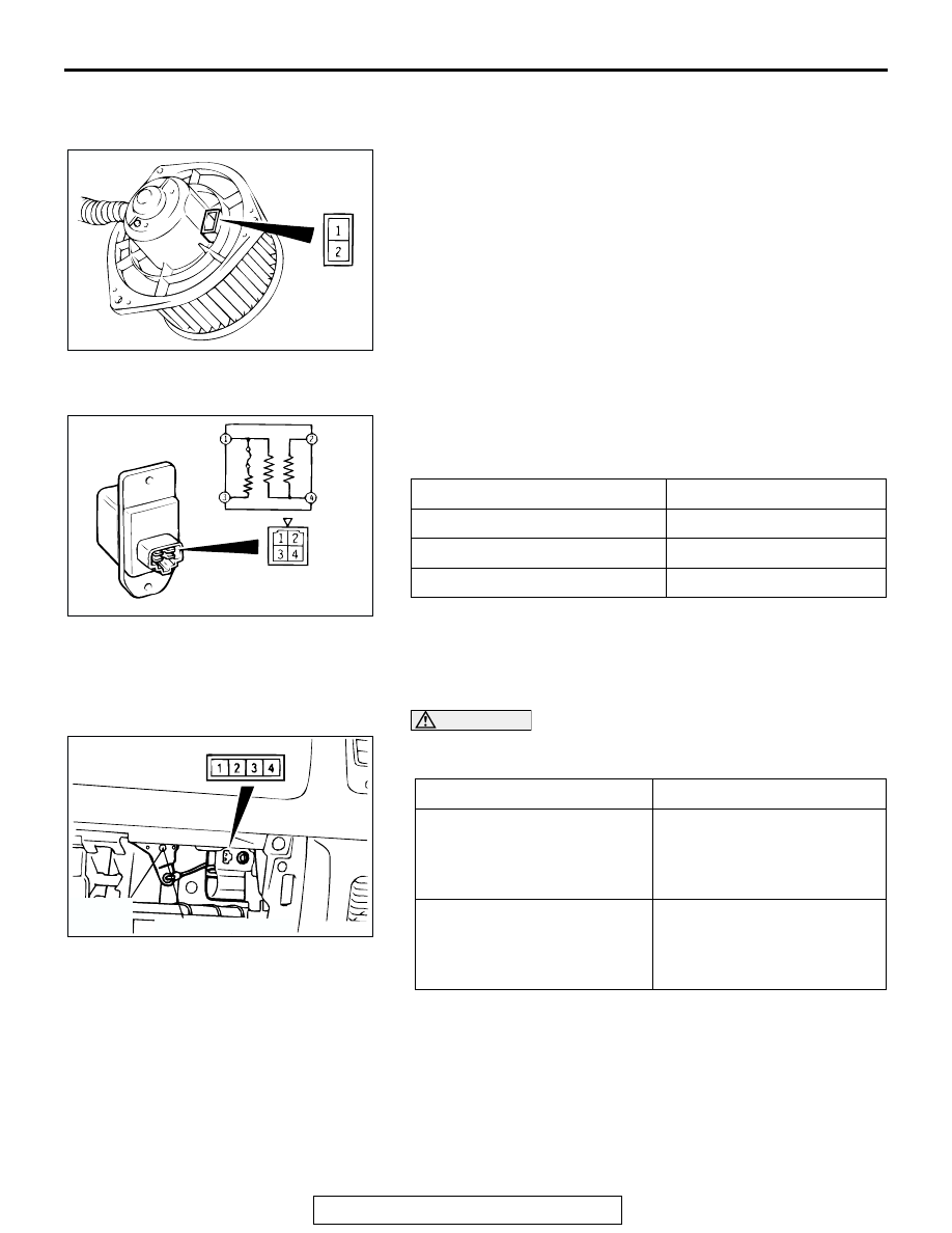
INSPECTION
M1556001100099
BLOWER FAN AND MOTOR CHECK
When battery voltage is applied between the terminals, check
that the motor operates. Also, check that there is no abnormal
noise.
RESISTOR CHECK
Use an ohmmeter to measure the resistance between the ter-
minals. Check that the measured value is at the standard
value.
INSIDE/OUTSIDE AIR CHANGEOVER DAMPER
MOTOR CHECK
CAUTION
Cut off the battery voltage when the damper is in the
inside/outside air position.
AC002855 AB
MEASUREMENT TERMINAL
STANDARD VALUE
Ω
Between terminals 3 and 2 (LO) 2.0
Between terminals 3 and 4 (ML) 1.1
Between terminals 3 and 1 (MH) 0.37
AC002856AB
BATTERY CONNECTION
LEVER POSITION
• Connect terminal 1 to the
positive battery terminal
• Connect terminal 2 to the
negative battery terminal
Moves to the outside air
position
• Connect terminal 1 to the
positive battery terminal
• Connect terminal 4 to the
negative battery terminal
Moves to the inside air
position
AC002857
OUTSIDE
AIR
POSTION
INSIDE AIR POSITION
AB