Mitsubishi Montero Sport (2004+). Manual - part 528


  Index      Mitsubishi     Mitsubishi Montero Sport - service repair manual 2004 year


Search            


Content   ..  526  527  528  529   ..


Mitsubishi Montero Sport (2004+). Manual - part 528


COMBINATION METER ASSEMBLY AND VEHICLE SPEED SENSOR

TSB Revision

CHASSIS ELECTRICAL

54-99

NOTE: After checking junction block connector D-06 and D-08, 
check the wires. If junction block connector D-06 and D-08 are 
damaged, repair or replace them. Refer to GROUP 00E, Har-
ness Connector Inspection 

P.00E-2

.

Q: Are the harness wires between combination meter 

connector C-04 (terminal No.24) and ignition switch 
(IG1) in good condition?
YES : 
Go to Step 9.
NO :  Repair them. The tachometer should work normally.

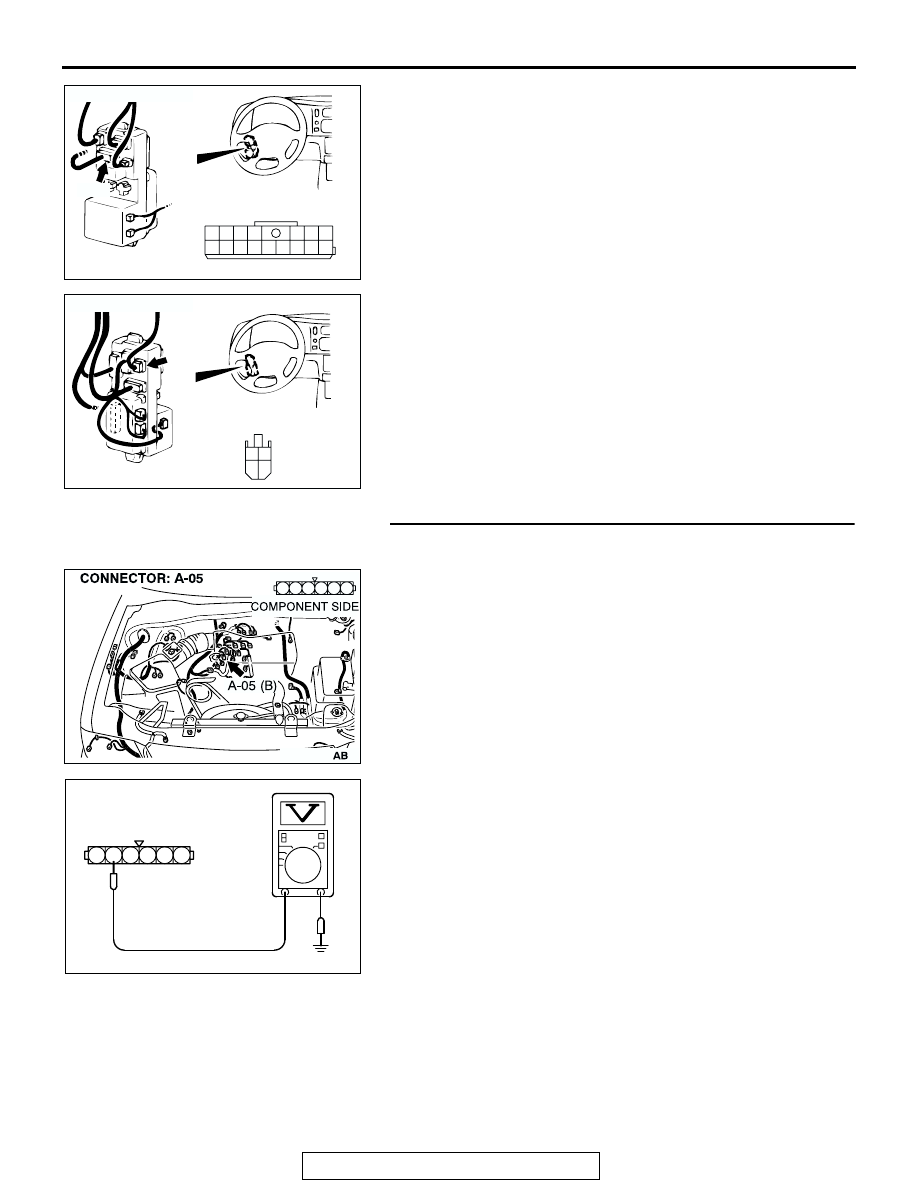
STEP 9. Check the circuit at ignition power transistor 
connector A-05.

(1) Disconnect connector A-05 and measure at the harness 

side.

(2) Turn the ignition switch to the "ON" position.

(3) Measure the voltage between terminal 5 and ground.

• Voltage should be four volts or more.

(4) Turn the ignition switch to the "LOCK" (OFF) position.
Q: Does the measured voltage correspond with this range?

YES : Replace the ignition power transistor. Then confirm 

that the malfunction symptom is eliminated.

NO :  Go to Step 10.

AC200772

1
8

3

4

5

7 6

10

15

16

14

12

13

11

9

2

COMPONENT SIDE

CONNECTOR: D-06

D-06

JUNCTION BLOCK
 (FRONT)

AB

AC200773

M

3

1

4

2

CONNECTOR: D-08

D-08

COMPONENT SIDE

AB

AC201844

1

3

4

2

6 5

AC202615

6 5 4 3 2 1

A-05 HARNESS CONNECTOR:
COMPONENT SIDE

AB

COMBINATION METER ASSEMBLY AND VEHICLE SPEED SENSOR

TSB Revision

CHASSIS ELECTRICAL

54-100

STEP 10. Check ignition power transistor connector A-05 
for loose, corroded or damaged terminals, or terminals 
pushed back in the connector.

Q:  Is combination meter connector A-05 in good 

condition?
YES : 
Go to Step 11.
NO :  Repair or replace it. Refer to GROUP 00E, Harness 

Connector Inspection 

P.00E-2

. The tachometer 

should work normally.

STEP 11. Check ignition power transistor connector A-05 
and combination meter connector C-05 for loose, corroded 
or damaged terminals, or terminals pushed back in the 
connector.

Q: Are ignition power transistor connector A-05 and 

combination meter connector C-05 in good condition?
YES : 
Go to Step 12.
NO :  Repair or replace them. Refer to GROUP 00E, 

Harness Connector Inspection 

P.00E-2

. The 

tachometer should work normally.

AC201844

1

3

4

2

6 5

AC201844

1

3

4

2

6 5

AC2018743

3 2

6 5 4

7

8

9

1110

1

12

1413

CONNECTOR: C-05

C-05 HARNESS CONNECTOR

C-05

AC201843 AB

COMBINATION METER ASSEMBLY AND VEHICLE SPEED SENSOR

TSB Revision

CHASSIS ELECTRICAL

54-101

STEP 12. Check the harness wire between combination 
meter connector C-05 (terminal No.14) and ignition power 
transistor connector A-05 (terminal No.5).

AC201844

1

3

4

2

6 5

AC2018743

3 2

6 5 4

7

8

9

1110

1

12

1413

CONNECTOR: C-05

C-05 HARNESS CONNECTOR

C-05

AC201843 AB

COMBINATION METER ASSEMBLY AND VEHICLE SPEED SENSOR

TSB Revision

CHASSIS ELECTRICAL

54-102

NOTE: After checking intermediate connector C-16 and joint 
connector (4) C-71, check the wires. If intermediate connector 
C-16 and joint connector (4) C-71 are damaged, repair or 
replace them. Refer to GROUP 00E, Harness Connector 
Inspection 

P.00E-2

.

Q: Is the harness wire between combination meter 

connector C-05 (terminal No.14) and ignition power 
transistor connector A-05 (terminal No.5) in good 
condition?
YES : 
There is no action to be taken.
NO :  Repair it. The tachometer should work normally.

AC201845

22

2021

10

9

8

1718

6 7

19

1415

4 5

1112

1 2 3

13

16

CONNECTOR: C-16

AB

C-16

AC003466AD

C-71

CONNECTOR: C-71


Content   ..  526  527  528  529   ..