Mitsubishi Montero Sport (2004+). Manual - part 520


  Index      Mitsubishi     Mitsubishi Montero Sport - service repair manual 2004 year


Search            


Content   ..  518  519  520  521   ..


Mitsubishi Montero Sport (2004+). Manual - part 520


IGNITION SWITCH

TSB Revision

CHASSIS ELECTRICAL

54-67

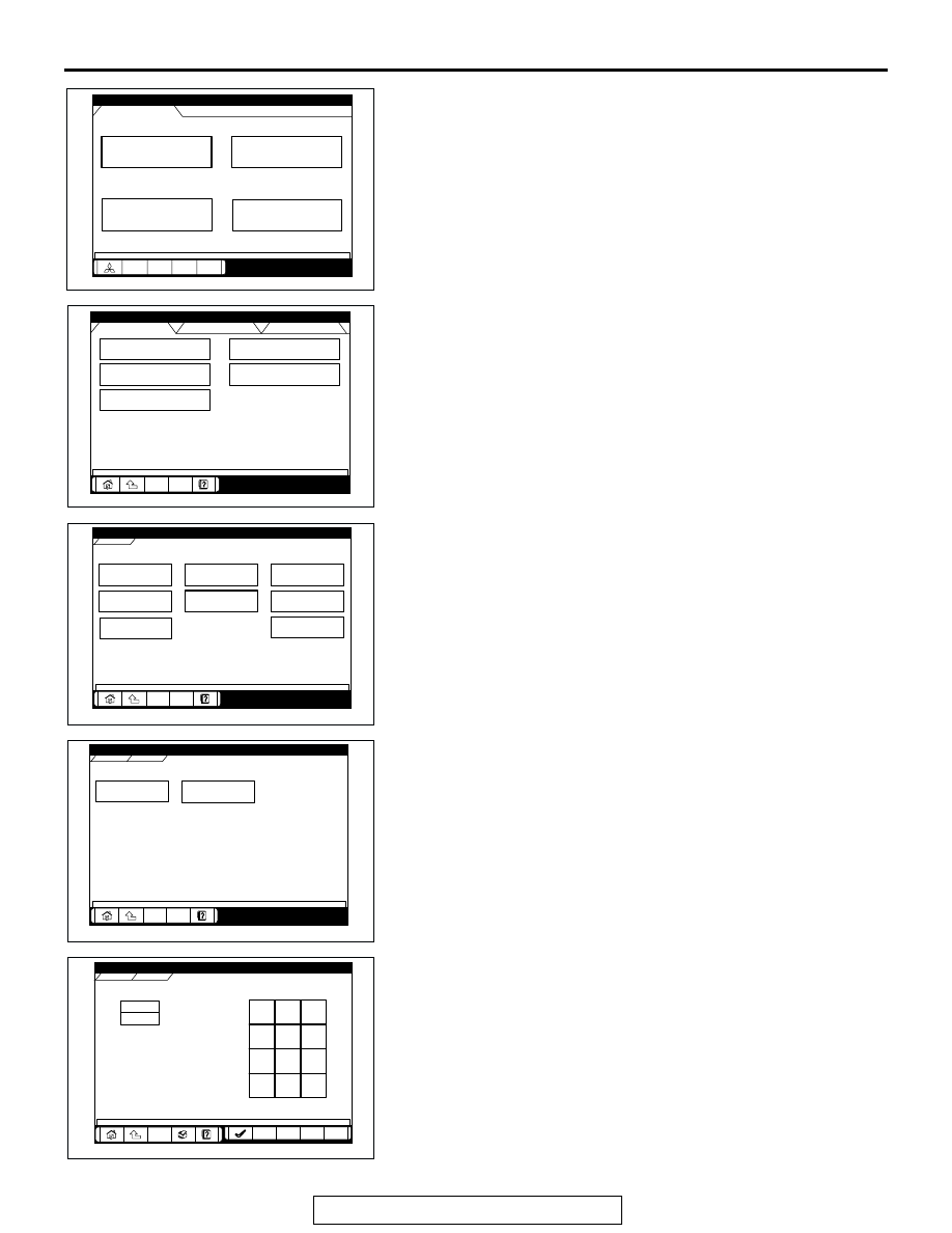
5. Select "System select."

6. Choose "IMMOBILIZER" from the "POWER TRAIN" tab.

7. Choose "Special Function" from "IMMOBILIZER" screen.

8. Choose "Key registration" from "Special Function" screen.

9. Enter the vehicle’s password (secret code) on the "Key 

registration" screen, and then click the check mark icon. 
Follow the prompts on the screen to insert key(s) into the 
ignition switch to begin key registration.

System select

Special function

CAN bus diagnosis

Function Select Menu

Menu

AC209666

Maintenance

AC

MFI

ELC-A/T

IMMOBILIZER

SS4II

CRUISE CNTRL

CHASSIS

BODY

System Select Menu

POWER TRAIN

AC209667

AC

Check Chart For

 Problem Sy

Data List

Special 

Function

Self-diagnosis

Voltmeter

Simulated Vehicle 

Speed Out

Drive Recorder

Resistor

POWERTRAIN

IMMOBILIZER

IMMOBILIZER

AC207298

AD

Key registration

Transponder ID 

addition

POWERTRAIN

Special Function

IMMOBILIZER

Special Function

AC207299

AE

POWERTRAIN

IMMOBILIZER

Special Function

7

8

9

4

5

6

1

2

3

0

Back

Back

Space

Space

Clear

Clear

Key registration

AC207300

AC

IGNITION SWITCH

TSB Revision

CHASSIS ELECTRICAL

54-68

10.If the key ID was registered successfully, "Progress" 

indication will turn active (gray). Then the registration 
process completes. If the key ID failed to be registered, 
"In-Complete" indication will turn active (gray).

11.The number of keys currently registered will be displayed. 

To register an additional key, replace the ignition key with 
the next key to be registered within five seconds. Key ID 
registration screen will be displayed, then register another 
key.
NOTE: A maximum of eight different keys can be registered.

12.This completes the registration operation. Turn the ignition 

switch "LOCK" (OFF) and leave it off for approximately ten 
seconds.

13.Check that the engine can be started with each of the 

ignition keys.

14.Check that the immobilizer system DTC and MFI system 

DTC did not set.

15.If not DTC is shown, terminate the scan tool MB991958.
16.Turn the ignition switch to "LOCK" (OFF) position.
17.Disconnect scan tool MB991958.

.

Registration of additional key(s) without using the scan 
tool
If the scan tool is not available, new key(s) can be registered by 
operating two keys which have been registered to the vehicle 
(A maximum of eight keys can be registered to one vehicle). 
Follow the procedure below to register new key(s) to the vehi-
cle.
NOTE: The registered key is the key that allows you to start the 
engine.
1. Turn on the ignition switch by using the first registered key 

(key A), and wait for five seconds.

2. Within 30 seconds, remove the key.
3. Within seven seconds after the ignition switch has been 

turned to the "LOCK" (OFF), insert the second registered 
key (key B) and turn on the ignition switch again. Now the 
theft-alarm indicator light should blink twice for one second. 
If it does not blink, you has failed to register. Repeat from 
step 1.

4. Turn on the key B. Within 30 seconds, remove the key.
5. Within seven seconds after the ignition switch has been 

turned to the "LOCK" (OFF) position, turn on the ignition 
switch by using a new key.

6. The immobilizer-ECU identifies the new key to accept or 

reject it, and operates the theft-alarm indicator (See the 
table below). 

POWERTRAIN

IMMOBILIZER

Special Function

IMMOBILIZER-ECU registration

Progress

In-Complete

Key registration

AC207302

AC

AC102935 AB

IGNITION SWITCH

TSB Revision

CHASSIS ELECTRICAL

54-69

7. A maximum of eight ignition keys can be registered to one 

vehicle (If you attempt to register the ninth key, the 
immobilizer-ECU rejects the key). Follow the procedure 
below to register another new key. 

(1) Within 30 seconds after the new key has been registered 

on step 6, remove the key.

(2) Within seven seconds after the ignition switch has been 

turned to the "LOCK" (OFF), insert another new key and 
turn on the ignition switch.

(3) To register more other ignition key(s), repeat steps 1 and 

2.

8. If any of the following conditions are satisfied, the additional 

key registration mode will terminate:

• The ignition switch has been on for more than 30 seconds.

• After the ignition key has been turned to the "LOCK" (OFF), 

the engine control relay is turned off.

• The scan tool has started communicating with vehicle sys-

tems.

9. After the registration mode has terminated, the additionally 

registered key(s) should allow you to start the engine.

TRANSPONDER LOCK CHECK

M1543024100164

Required Special Tools:

• MB991958: Scan Tool (MUT-III Sub Assembly)

• MB991824: Vehicle Communication Interface (V.C.I.)

• MB991827: MUT-III USB Cable

• MB991911: MUT-III Main Harness B (Vehicles without 

CAN communication system)

CAUTION

To prevent damage to scan tool MB991958, always turn the 
ignition switch to "LOCK" (OFF) position before connect-
ing or disconnecting scan tool MB991958.
Follow the procedure below to judge if the ignition key can be 
overwritten (i.e. the ignition key is correct) or not.

The new key is:

Registration is:

Additional 
registration 
mode: 

Theft-alarm indicator: 

Not registered yet

Accepted

Continues

Comes on for 3 seconds after the ECU 
judges that the key has not been 
registered yet.

Already registered

Rejected

Continues

Comes on for 3 seconds after the ECU 
judges that the key has already been 
registered

Read error

Rejected

Continues

Blinks three times after the ECU has 
failed to identify the key.

Eight ignition keys have 
been registered

Rejected

Continues

Does not come on and blink

IGNITION SWITCH

TSB Revision

CHASSIS ELECTRICAL

54-70

1. Connect the scan tool MB991958 to the data link connector.
2. Turn the ignition switch to "ON" position.
3. Select "Interactive Diagnosis" from the start-up screen.

4. Select "System select." 

5. Choose "IMMOBILIZER" from the "POWER TRAIN" tab.

AK303629AB

MB991911

MB991827

MB991824 

16-PIN

System select

Special function

CAN bus diagnosis

Function Select Menu

Menu

AC209666

Maintenance

AC

MFI

ELC-A/T

IMMOBILIZER

SS4II

CRUISE CNTRL

CHASSIS

BODY

System Select Menu

POWER TRAIN

AC209667

AC


Content   ..  518  519  520  521   ..