Mitsubishi Montero Sport (2004+). Manual - part 516


  Index      Mitsubishi     Mitsubishi Montero Sport - service repair manual 2004 year


Search            


Content   ..  514  515  516  517   ..


Mitsubishi Montero Sport (2004+). Manual - part 516


IGNITION SWITCH

TSB Revision

CHASSIS ELECTRICAL

54-51

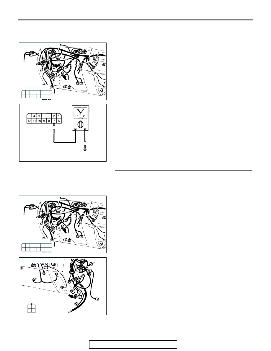
STEP 2. Check the immobilizer-ECU power supply circuit 
by backprobing.

(1) Do not disconnect immobilizer-ECU connector C-107.
(2) Turn the ignition switch to the "ON" position.

(3) Measure the voltage between terminal 7 and ground by 

backprobing.

• The measured value should be approximately 12 volts 

(battery positive voltage).

Q: Does the measured voltage correspond with this range?

YES : Go to Step 5.
NO :  Go to Step 3.

STEP 3. Check immobilizer-ECU connector C-107 and 
engine control relay connector C-59 for loose, corroded or 
damaged terminals, or terminals pushed back in the 
connector.

Q: Are immobilizer-ECU connector C-107 and engine 

control relay connector C-59 in good condition?
YES : 
Repair or replace them. Refer to GROUP 00E, 

Harness Connector Inspection 

P.00E-2

. Confirm that 

scan tool MB991958 communicates normally.

NO :  Go to Step 4.

AC202606

C-107

1

2
7

6

3

4

5

12 11 10 9 8

CONNECTOR: C-107

AC

COMPONENT SIDE

AC002737

AC

C-107 HARNESS CONNECTOR:
COMPONENT SIDE

AC202606

C-107

1

2
7

6

3

4

5

12 11 10 9 8

CONNECTOR: C-107

AC

COMPONENT SIDE

AC202099

2
4

1
3

CONNECTOR: C-59

AB

C-59

COMPONENT SIDE

IGNITION SWITCH

TSB Revision

CHASSIS ELECTRICAL

54-52

STEP 4. Check the harness wires between 
immobilizer-ECU connector C-107 (terminal No. 7) and MFI 
relay connector C-59 (terminal No.1).

NOTE:  After checking intermediate connector C-72 and joint 
connector C-14, check the wires. If intermediate connector 
C-72 and joint connector C-14 are damaged, repair or replace 
them. Refer to GROUP 00E, Harness Connector Inspection 

P.00E-2

.

Q: Are the harness wires between immobilizer-ECU 

connector C-107 (terminal No.7) and MFI relay 
connector C-59 (terminal No.1) damaged?
YES : 
Replace them. Confirm that scan tool MB991958 

communicates normally.

NO :  There is no action to be taken.

AC202606

C-107

1

2
7

6

3

4

5

12 11 10 9 8

CONNECTOR: C-107

AC

COMPONENT SIDE

AC202099

2
4

1
3

CONNECTOR: C-59

AB

C-59

COMPONENT SIDE

AC202100

9 10

8

6 7

31 32

30

29

21

20

19

18

5

4

2

1

3

27

26

24

23

25

16

15

14

13

12

28

17

33

22

11

CONNECTOR: C-14

AB

C-14

8

19

7

6

5

16

15

17 18

4

3

2

10 11 12 13

1
9

14

AC201910

CONNECTOR: C-72

AB

C-72 (B)

IGNITION SWITCH

TSB Revision

CHASSIS ELECTRICAL

54-53

STEP 5. Check the immobilizer-ECU ground circuit by 
backprobing.

(1) Do not disconnect immobilizer-ECU connector C-107. 

(2) Measure the resistance between terminal 3 and ground by 

backprobing.

• The measured value should be 2 ohms or less.

Q: Does the measured resistance value correspond with 

this range?
YES : 
Go to Step 6.
NO :  Go to Step 8.

STEP 6. Check immobilizer-ECU connector C-107 for 
loose, corroded or damaged terminals, or terminals 
pushed back in the connector.

Q: Is immobilizer-ECU connector C-107 in good condition?

YES : Go to Step 7.
NO :  Repair or replace it. Refer to GROUP 00E, Harness 

Connector Inspection 

P.00E-2

. Confirm that scan tool 

MB991958 communicates normally.

STEP 7. Check the harness wire between immobilizer-ECU 
connector C-107 (terminal No.3) and ground.

Q: Is the harness wire between immobilizer-ECU connector 

C-107 and ground damaged?
YES : 
Repair it. Confirm that scan tool MB991958 

communicates normally.

NO :  There is no action to be taken.

AC202606

C-107

1

2
7

6

3

4

5

12 11 10 9 8

CONNECTOR: C-107

AC

COMPONENT SIDE

AC309487     

6

1

12

5

11

10

9

8

7

2

3 4

C-107 HARNESS CONNECTOR:

COMPONENT SIDE

AC

AC202606

C-107

1

2
7

6

3

4

5

12 11 10 9 8

CONNECTOR: C-107

AC

COMPONENT SIDE

AC202606

C-107

1

2
7

6

3

4

5

12 11 10 9 8

CONNECTOR: C-107

AC

COMPONENT SIDE

IGNITION SWITCH

TSB Revision

CHASSIS ELECTRICAL

54-54

STEP 8. Check the harness wires between 
immobilizer-ECU connector C-107 (terminal No.5) and 
powertrain control module connector C-92 (terminal 
No.111).

Q: Are the harness wires between immobilizer-ECU 

connector C-107 (terminal No.5) and powertrain control 
module connector C-92 (terminal No.111) damaged?
YES : 
Repair them. Confirm that scan tool MB991958 

communicates normally.

NO :  Go to Step 9.

STEP 9. Replace the immobilizer-ECU or powertrain 
control module.

Replace the immobilizer-ECU or powertrain control module.
Q: Did the communication with MUT-II become possible 

after replacing the immobilizer-ECU or the powertrain 
control module?
YES : 
Register the password (secret code) and encrypted 

code 

P.54-65

. Confirm that scan tool MB991958 

communicates normally.

NO :  Go to Step 10.

AC202606

C-107

1

2
7

6

3

4

5

12 11 10 9 8

CONNECTOR: C-107

AC

COMPONENT SIDE

AC202103

108

101

109

102

110

121

111

103

112

115114113

125124

104

118

105

117

120

107 106

122

119

130

129

123

128

116

127126

CONNECTOR: C-92

AB

C-92 (GR)

C-92 (GR) HARNESS SIDE


Content   ..  514  515  516  517   ..