Mitsubishi Montero Sport (2004+). Manual - part 451


  Index      Mitsubishi     Mitsubishi Montero Sport - service repair manual 2004 year


Search            


Content   ..  449  450  451  452   ..


Mitsubishi Montero Sport (2004+). Manual - part 451


DOOR

TSB Revision

BODY

42-59

DIAGNOSIS

STEP 1. Confirm which door lock actuator is defective.
Q: Which door fails to lock correctly?

Front driver's door : Go to Step 2.
Front passenger's door : Go to Step 6.
Rear right door : Go to Step 10.
Rear left door : Go to Step 14.
Liftgate : Go to Step 18.

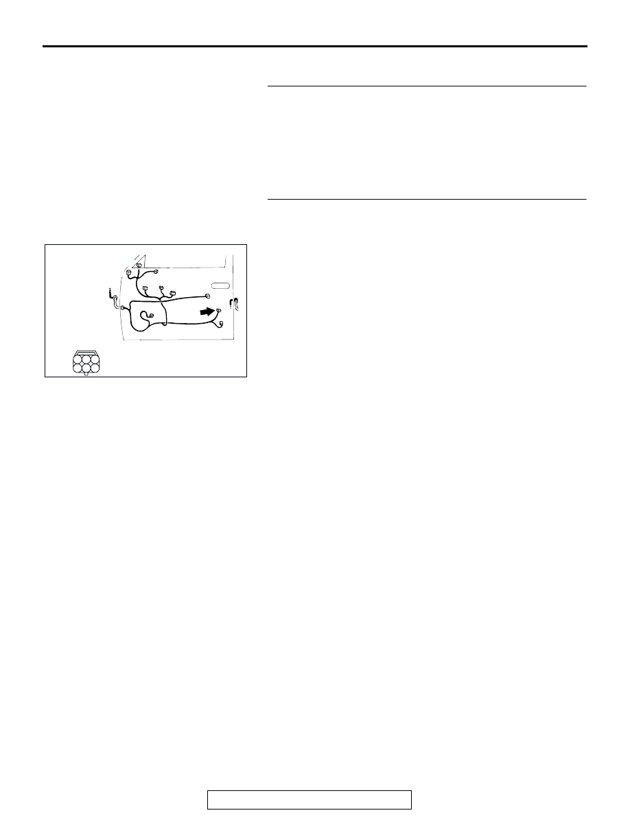
STEP 2. Check door lock actuator (front: LH) connector 
F-12 for loose, corroded or damaged terminals, or 
terminals pushed back in the connector.
Q: Is the connector in good condition?

YES : Go to step 3.
NO :  Repair or replace the damaged components. Refer to 

GROUP 00E 

P.00E-2

, Harness Connector inspection. 

Then go to Step 22.

AC309370

CONNECTOR: F-12

F-12

FRONT DOOR <LH>

AC

1

3 2

4

6 5

COMPONENT SIDE

DOOR

TSB Revision

BODY

42-60

STEP 3. Check the front door lock actuator switch (front: 
LH).
(1) Remove the door latch assembly (Refer to 

P.42-140

).

(2) Follow the table to check the resistance when the door lock 

actuator (front: LH) is operated (lock/unlock).

Q: Is the front door lock actuator switch (front: LH) 

damaged?
YES : 
Replace front door lock actuator assembly (front: LH), 

go to Step 22.

NO :  Go to Step 4.

LEVER      
POSITION

BATTERY 
CONNECTION

LEVER 
OPERATION

At the 
"UNLOCK" 
position

• Connect terminal 

No. 6 and the 
positive battery 
terminal.

• Connect terminal 

No. 4 and the 
negative battery 
terminal.

The lever moves 
from the 
"UNLOCK" 
position to the 
"LOCK" position.

At the "LOCK" 
position

• Connect terminal 

No. 4 and the 
positive battery 
terminal.

• Connect terminal 

No. 6 and the 
negative battery 
terminal.

The lever moves 
from the "LOCK" 
position to the 
"UNLOCK" 
position.

ACX00543

LOCK

UNLOCK

VIEW A

A

AE

LEVER

DOOR

TSB Revision

BODY

42-61

STEP 4. Check ETACS-ECU connectors D-10 <Vehicles 
without keyless entry system> and D-27 <Vehicles with 
keyless entry system> for loose, corroded or damaged 
terminals, or terminals pushed back in the connector.
Q: Are ETACS-ECU connectors D-10 <Vehicles without 

keyless entry system> and D-27 <Vehicles with keyless 
entry system> in good condition?
YES : 
Go to Step 5.
NO :  Repair or replace the damaged components. Refer to 

GROUP 00E 

P.00E-2

, Harness Connector inspection. 

Then go to Step 22.

AC202002

6 5 4

1

2

7

3
8

41

43

51

42

50

44

52

46 45

53

49

47

30

48

56

55

D-27 (B)

D-10

JUNCTION 
BLOCK (REAR)

CONNECTORS: D-10, D-27

AB

D-27 COMPONENT  SIDE

D-10 COMPONENT SIDE

21

22

23

24

25

26

27

28

DOOR

TSB Revision

BODY

42-62

STEP 5. Check the harness wire between ETACS-ECU 
connectors D-10 (terminals No.21 and No.24) <Vehicles 
without keyless entry system> or D-27 (terminals No.41 
and No.42) <Vehicles with keyless entry system> and door 
lock actuator (front: LH) connector F-12 (terminals No.4 
and No.6).

AC202002

6 5 4

1

2

7

3
8

41

43

51

42

50

44

52

46 45

53

49

47

30

48

56

55

D-27 (B)

D-10

JUNCTION 
BLOCK (REAR)

CONNECTORS: D-10, D-27

AB

D-27 COMPONENT  SIDE

D-10 COMPONENT SIDE

21

22

23

24

25

26

27

28

AC309370

CONNECTOR: F-12

F-12

FRONT DOOR <LH>

AC

1

3 2

4

6 5

COMPONENT SIDE


Content   ..  449  450  451  452   ..