Mitsubishi Montero Sport (2004+). Manual - part 419


  Index      Mitsubishi     Mitsubishi Montero Sport - service repair manual 2004 year


Search            


Content   ..  417  418  419  420   ..


Mitsubishi Montero Sport (2004+). Manual - part 419


DIFFERENTIAL CARRIER ASSEMBLY

TSB Revision

FRONT AXLE

26-57

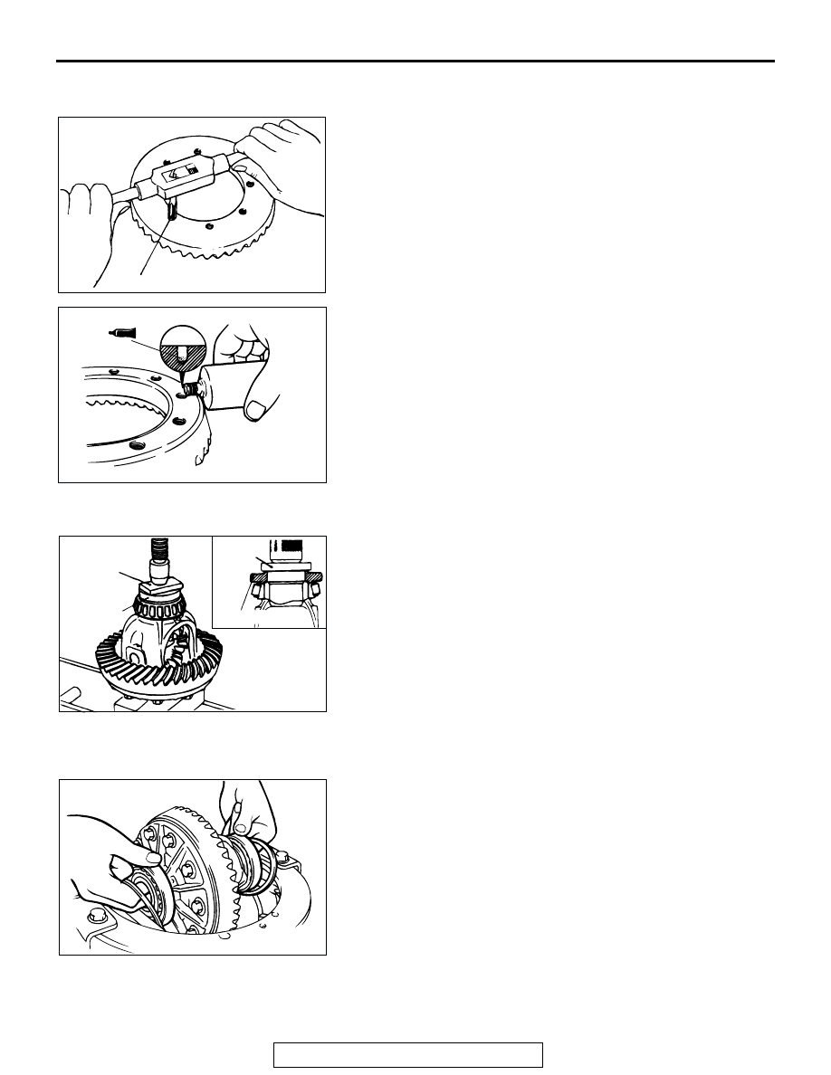
>>H<< DRIVE GEAR INSTALLATION
1. Clean the drive gear attaching bolts.
2. Remove the adhesive adhered to the threaded holes of the 

drive gear by turning the special tool MB990813 (tap M10 x 
1.25), and then clean the threaded holes by applying 
compressed air.

3. Apply the 3M

 AAD Part number 8730 or AAD Part number 

8731 or equivalent to the threaded holes of the drive gear.

4. Install the drive gear onto the differential case with the 

mating marks properly aligned. Tighten the bolts to the 
specified torque in a diagonal sequence.

Tightening torque: 78 

 88 Nm (58  65 ft-lb)

.

>>I<< SIDE BEARING INNER RACE INSTALLATION
Use special tool MB990802 to press-fit the side bearing inner 
races into the differential case.

.

>>J<< DRIVE GEAR BACKLASH ADJUSTMENT
Adjust the drive gear backlash by the following procedures:
1. Install the side bearing spacers, which are thinner than 

those removed, to the side bearing outer races, and then 
mount the differential case assembly into the gear carrier.
NOTE: Select side bearing spacers with the same thickness 
for both the drive pinion side and the drive gear side.

ACX01068AB

TAP

AC000438 AB

ACX01069AC

MB990802

MB990802

PIECE OF
METAL

PIECE OF
METAL

ACX01070 AB

DIFFERENTIAL CARRIER ASSEMBLY

TSB Revision

FRONT AXLE

26-58

2. Push the differential case assembly to one side, and 

measure the clearance between the gear carrier and the 
side bearing adjusting spacer with a feeler gauge.

3. Measure the thickness of the side bearing adjusting spacers 

on one side, select two pairs of spacers which correspond to 
that thickness plus one half of the clearance plus 0.05 mm 
(0.002 inch), and then install one pair each to the drive 
pinion side and the drive gear side.

4. Install the side bearing adjusting spacers and differential 

case assembly, as shown in the illustration, to the gear 
carrier.

5. Tap the side bearing adjusting spacers with special tool 

MB990939 to fit them to the side bearing outer race.

6. Align the mating marks on the gear carrier and the bearing 

cap, and then tighten the bearing cap.

ACX01071AB

ACX01072 AC

CLEARANCE/2 + 0.05 mm
(0.002 in) = THICKNESS OF
THE SPACER ON ONE SIDE

ACX01070 AB

ACX01073 AB

MB990939

ACX01074AB

DIFFERENTIAL CARRIER ASSEMBLY

TSB Revision

FRONT AXLE

26-59

7. With the drive pinion locked in place, measure the drive gear 

backlash with a dial indicator on the drive gear.
NOTE: Measure at four points or more on the circumference 
of the drive gear.

Standard value: 0.11 

 0.16 mm (0.004  0.006 inch)

8. Change the side bearing adjusting spacers as illustrated, 

and then adjust the drive gear backlash between the drive 
gear and the drive pinion.
NOTE: When increasing the number of side bearing adjust-
ing spacers, use the same number for each, and as few as 
possible.

9. Check the drive gear and drive pinion for tooth contact. If 

poor contact is evident, make adjustment. (Refer to 

P.26-41

.)

10.Measure the drive gear runout at the shoulder on the 

reverse side of the drive gear.

Limit: 0.05 mm (0.002 inch)

11.If the drive gear runout exceeds the limit, reinstall by 

changing the phase of the drive gear and differential case, 
and remeasure.

12.If adjustment is not possible, replace the differential case or 

replace the drive gear and drive pinion as a set.

ACX01034AB

ACX01075

IF BACKLASH IS TOO SMALL

IF BACKLASH IS TOO LARGE

THINNER
SPACER

THICKER
SPACER

AB

THINNER
SPACER

THICKER
SPACER

ACX01036 AB

SPECIFICATIONS

TSB Revision

FRONT AXLE

26-60

SPECIFICATIONS

FASTENER TIGHTENING SPECIFICATIONS

M1261005400224

ITEM

SPECIFICATION

Differential carrier
Cover bolt

19 N

⋅m (14 ft-lb)

Differential case bolt

78 

− 88 N⋅m (58 − 65 ft-lb)

Drain plug

59 

− 64 N⋅m (44 − 51 ft-lb)

Drive pinion self-locking nut

216 N

⋅m (159 ft-lb)

Filler plug

49 N

⋅m (36 ft-lb)

Front suspension crossmember nut

98 

− 118 N⋅m (72 − 87 ft-lb)

Front propeller shaft connection nut

49 

− 59 N⋅m (36 − 43 ft-lb)

Differential mounting bracket <LH> bolt

88 N

⋅m (65 ft-lb)

Differential mounting bracket <RH> nut

93 N

⋅m (69 ft-lb)

Differential mount insulator assembly

35 N

⋅m (26 ft-lb)

Differential support bracket bolt

69 N

⋅m (51 ft-lb)

Differential support bracket nut

44 N

⋅m (32 ft-lb)

Dynamic damper nut

22 N

⋅m (16 ft-lb)

Bearing cap bolt

54 

− 64 N⋅m (40 − 47 ft-lb)

Drive shaft
Driveshaft and inner shaft connection nut

49 

− 59 N⋅m (36 − 43 ft-lb)

Front axle hub
ABS Rotor bolt

22 N

⋅m (16 ft-lb)

Brake disc and front hub assembly connection nut

49 

− 59 N⋅m (36 − 43 ft-lb)

Caliper assembly bolt

88 N

⋅m (65 ft-lb)

Hub cap bolt

49 

− 59 N⋅m (36 − 43 ft-lb)

Jam nut

127 

− 196 N⋅m → 0 N⋅m → 25 

N

⋅m (94 − 145 ft-lb → 0 in-lb → 

18 ft-lb)

Inner shaft
Breather pipe bolt

12 N

⋅m (106 ft-lb)

Housing tube bolt

 88 N

⋅m ( 65 ft-lb)

Differential mounting bracket nut

93 N

⋅m (69 ft-lb)

Heat protector bolt

12 N

⋅m (106 in-lb)

Knuckle
Lower arm ball joint and knuckle connection nut

118 

− 177 N⋅m (87 − 131 ft-lb)

Shock absorber nut (lower)

88 

− 103 N⋅m (65 − 76 ft-lb)

Stabilizer bracket bolt

12 N

⋅m (106 in-lb)

Tie rod end connection nut

44 N

⋅m (32 ft-lb)

Upper arm ball joint and knuckle connection nut

59 

− 88 N⋅m (44 − 65 ft-lb)


Content   ..  417  418  419  420   ..