Mitsubishi Montero Sport (2004+). Manual - part 345


  Index      Mitsubishi     Mitsubishi Montero Sport - service repair manual 2004 year


Search            


Content   ..  343  344  345  346   ..


Mitsubishi Montero Sport (2004+). Manual - part 345


MULTIPORT FUEL INJECTION (MFI) DIAGNOSIS

TSB Revision

MULTIPORT FUEL INJECTION (MFI)

13A-793

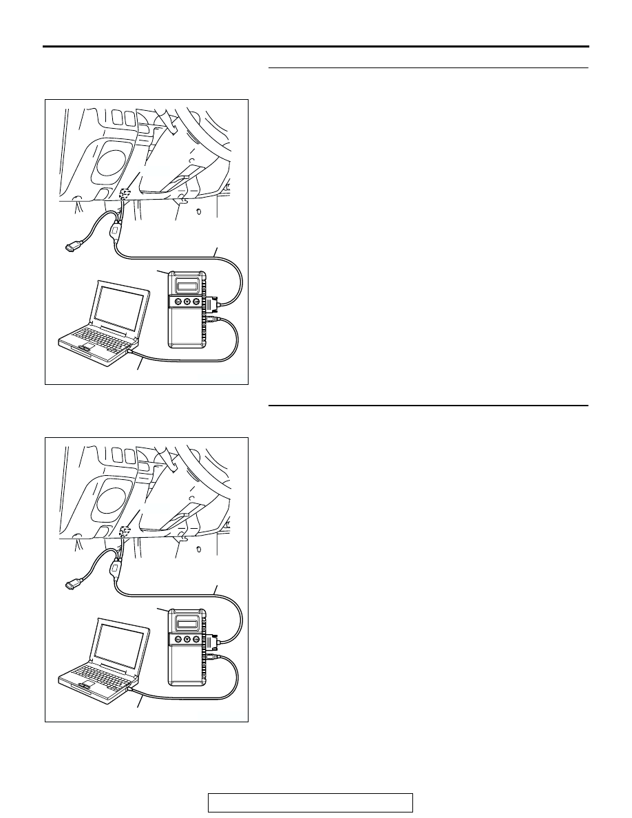
STEP 7. Using scan tool MB991958, check data list item 39: 
Right Bank heated oxygen sensor (front).
(1) Start the engine and run at idle.
(2) Set scan tool MB991958 to the data reading mode for item 

39, Right Bank Heated Oxygen Sensor (front).

• Warm up the engine. When the engine is decelerated 

suddenly from 4000 r/min, the output voltage should 
increase from 200 millivolts or less to 600 

− 1000 milli-

volts in a few seconds.

(3) Turn the ignition switch to the "LOCK" (OFF) position.
Q: Is the sensor operating properly?

YES : Go to Step 8.
NO :  Refer to DTC P0130 

− Heated Oxygen Sensor Circuit 

(bank 1, sensor 1) 

P.13A-178

, DTC P0131 

− Heated 

Oxygen Sensor Circuit low voltage (bank 1, sensor 1) 

P.13A-190

, DTC P0132 

− Heated Oxygen Sensor 

Circuit High Voltage (bank 1, sensor 1) 

P.13A-198

P0133 

− Heated Oxygen Sensor Circuit Slow 

Response (bank 1, sensor 1) 

P.13A-203

, P0134 

− 

Heated Oxygen Sensor Circuit No Activity Detected 
(bank 1, sensor 1) 

P.13A-209

.

STEP 8. Using scan tool MB991958, check data list item 11: 
Left Bank Heated oxygen sensor (front).
(1) Start the engine and run at idle.
(2) Set scan tool MB991958 to the data reading mode for item 

11, Left Bank Heated Oxygen Sensor (front).

• Output voltage should measure 0.6 − 1.0 volt when sud-

den revving.

(3) Turn the ignition switch to the "LOCK" (OFF) position.
Q: Is the sensor operating properly?

YES : Go to Step 9.
NO :  Refer to DTC P0150 

− Heated Oxygen Sensor Circuit 

(bank 2, sensor 1) 

P.13A-275

, DTC P0151 

− Heated 

Oxygen Sensor Circuit low voltage (bank 2, sensor 1) 

P.13A-287

, DTC P0152 

− Heated Oxygen Sensor 

Circuit High Voltage (bank 2, sensor 1) 

P.13A-295

P0153 

− Heated Oxygen Sensor Circuit Slow 

Response (bank 2, sensor 1) 

P.13A-300

, P0154 

− 

Heated Oxygen Sensor Circuit No Activity Detected 
(bank 2, sensor 1) 

P.13A-306

.

AK303629AB

MB991911

MB991827

MB991824 

16-PIN

AK303629AB

MB991911

MB991827

MB991824 

16-PIN

MULTIPORT FUEL INJECTION (MFI) DIAGNOSIS

TSB Revision

MULTIPORT FUEL INJECTION (MFI)

13A-794

STEP 9. Using scan tool MB991958, check data list item 39: 
Right Bank Heated oxygen sensor (front).
(1) Start the engine and run at idle.
(2) Set scan tool MB991958 to the data reading mode for item 

39, Right Bank Heated Oxygen Sensor (front).

• Voltage should fluctuate between 0 − 0.4 volt and 0.6 − 

1.0 volt while after the engine has been warmed.

(3) Turn the ignition switch to the "LOCK" (OFF) position.
Q: Is the sensor operating properly?

YES : Go to Step 10.
NO :  Go to Step 12.

STEP 10. Check the EGR system.
Refer to GROUP 17, Emission Control System 

− EGR System 

Check 

P.17-112

.

Q: Is the EGR system normal?

YES : Go to Step 11.
NO :  Repair or replace. Then confirm that the malfunction 

symptom is eliminated.

AK303629AB

MB991911

MB991827

MB991824 

16-PIN

MULTIPORT FUEL INJECTION (MFI) DIAGNOSIS

TSB Revision

MULTIPORT FUEL INJECTION (MFI)

13A-795

STEP 11. Using scan tool MB991958, check data list item 
69: Right Bank Heated oxygen sensor (rear).

CAUTION

To prevent damage to scan tool MB991958, always turn the 
ignition switch to the "LOCK" (OFF) position before con-
necting or disconnecting scan tool MB991958.
(1) Connect scan tool MB9919958 to the data link connector.
(2) Start the engine and run at idle.
(3) Set scan tool MB991958 to the data reading mode for item 

69, Right Bank Heated Oxygen Sensor (rear).

• Average voltage should measure 0.6 volt or less, when 

idling.

(4) Turn the ignition switch to the "LOCK" (OFF) position.
Q: Is the sensor operating properly?

YES : Go to Step 16.
NO :  Replace the right bank heated oxygen sensor (front). 

Then confirm that the malfunction symptom is 
eliminated.

STEP 12. Using scan tool MB991958, check data list item 
11: Left Bank Heated oxygen sensor (front).
(1) Start the engine and run at idle.
(2) Set scan tool MB991958 to the data reading mode for item 

11, Left Bank Heated Oxygen Sensor (front).

• Warm up the engine. When the engine is decelerated 

suddenly from 4000 r/min, the output voltage should 
increase from 200 millivolts or less to 600 

− 1000 milli-

volts in a few seconds.

(3) Turn the ignition switch to the "LOCK" (OFF) position.
Q: Is the sensor operating properly?

YES : Go to Step 13.
NO :  Go to Step 15.

AK303629AB

MB991911

MB991827

MB991824 

16-PIN

AK303629AB

MB991911

MB991827

MB991824 

16-PIN

MULTIPORT FUEL INJECTION (MFI) DIAGNOSIS

TSB Revision

MULTIPORT FUEL INJECTION (MFI)

13A-796

STEP 13. Check the EGR system.
Refer to GROUP 17, Emission Control System 

− EGR System 

Check 

P.17-112

.

Q: Is the EGR system normal?

YES : Go to Step 14.
NO :  Repair or replace. Then confirm that the malfunction 

symptom is eliminated.

STEP 14. Using scan tool MB991958, check data list item 
59: Left Bank Heated oxygen sensor (rear).

CAUTION

To prevent damage to scan tool MB991958, always turn the 
ignition switch to the "LOCK" (OFF) position before con-
necting or disconnecting scan tool MB991958.
(1) Connect scan tool MB991958 to the data link connector.
(2) Start the engine and run at idle.
(3) Set scan tool MB991958 to the data reading mode for item 

59, Left Bank Heated Oxygen Sensor (rear).

• Average voltage should measure 0.6 volt or less, when 

idling.

(4) Turn the ignition switch to the "LOCK" (OFF) position.
Q: Is the sensor operating properly?

YES : Go to Step 16.
NO :  Replace the left bank heated oxygen sensor (front). 

Then confirm that the malfunction symptom is 
eliminated.

STEP 15. Check the fuel pressure.
Refer to On-vehicle Service 

− Fuel Pressure Test 

P.13A-884

.

Q: Is the fuel pressure normal?

YES : Go to Step 16.
NO :  Repair or replace. Then confirm that the malfunction 

symptom is eliminated.

AK303629AB

MB991911

MB991827

MB991824 

16-PIN


Content   ..  343  344  345  346   ..