Mitsubishi Montero Sport (2004+). Manual - part 337


  Index      Mitsubishi     Mitsubishi Montero Sport - service repair manual 2004 year


Search            


Content   ..  335  336  337  338   ..


Mitsubishi Montero Sport (2004+). Manual - part 337


MULTIPORT FUEL INJECTION (MFI) DIAGNOSIS

TSB Revision

MULTIPORT FUEL INJECTION (MFI)

13A-761

INSPECTION PROCEDURE 12: When the Engine Is Hot, It Stalls at Idle (Die Out).

.

COMMENT

• In cases such as the above, the ignition system, 

air/fuel mixture, idle air control motor or compres-
sion pressure may be faulty. In addition, if the 
engine suddenly stalls, the cause may also be a 
loose connector.

.

TROUBLESHOOTING HINTS (The most likely 
causes for this case: )

• Malfunction of the ignition system.

• Malfunction of air/fuel ratio control system.

• Malfunction of the IAC system.

• Vacuum leak.

• Improper connector contact.

DIAGNOSIS

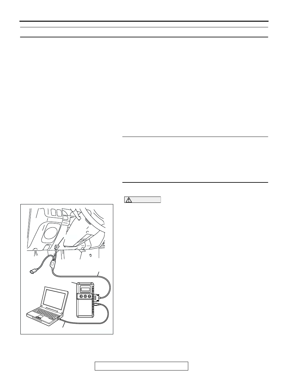
Required Special Tools:

• MB991958: Scan Tool (MUT-III Sub Assembly)

• MB991824: V.C.I

• MB991827: USB Cable

• MB991911: Main Harness B

STEP 1. Check if the battery terminal is disconnected.
Q: Has the battery terminal been disconnected lately?

YES : Start the engine and let it run at idle for approximate 

10 minutes after engine warm up. Then, if a 
malfunction occurs, go to step 2.

NO :  Go to Step 2.

STEP 2. Using scan tool MB991958, read the diagnostic 
trouble code (DTC).

CAUTION

To prevent damage to scan tool MB991958, always turn the 
ignition switch to the "LOCK" (OFF) position before con-
necting or disconnecting scan tool MB991958.
(1) Connect scan tool MB991958 to the data link connector.
(2) Turn the ignition switch to the "ON" position.
(3) Read the DTC.
(4) Turn the ignition switch to the "LOCK" (OFF) position.
Q: Is DTC set?

YES : Refer to Diagnostic Trouble Code Chart 

P.13A-26

NO :  Go to Step 3.

AK303629AB

MB991911

MB991827

MB991824 

16-PIN

MULTIPORT FUEL INJECTION (MFI) DIAGNOSIS

TSB Revision

MULTIPORT FUEL INJECTION (MFI)

13A-762

STEP 3. Check the idle air control (IAC) motor operation 
sound.
(1) Check that the engine coolant temperature is 20

°C (68°F) 

or below.
NOTE: If necessary, you can disconnect the engine coolant 
temperature sensor connector and connect the harness 
side of the connector to another engine coolant temperature 
sensor that is at 20

°

C (68

°

F) or below.

(2) Check that the operation sound of the IAC motor can be 

heard after the ignition is switched to the "ON" position (but 
without starting the engine).

• An operation sound should be heard.

(3) Turn the ignition switch to the "LOCK" (OFF) position.
Q: Did you hear the operation sound?

YES : Go to Step 4.
NO :  Refer to DTC P0506 

− Idle Control System RPM 

Lower Than Expected

P.13A-640

 , DTC P0507 

− Idle 

Control System RPM Higher Than 
Expected

P.13A-651

 .

STEP 4. Using scan tool MB991958, check actuator test 
items 01, 02, 03, 04, 05, 06: Injector.

CAUTION

To prevent damage to scan tool MB991958, always turn the 
ignition switch to the "LOCK" (OFF) position before con-
necting or disconnecting scan tool MB991958.
(1) Connect scan tool MB991958 to the data link connector.
(2) Turn the ignition switch to the "ON" position.
(3) Check following items in the actuator test. Refer to Actuator 

Test Reference Table 

P.13A-854

.

a. Items 01, 02, 03, 04, 05, 06: Injector.

(4) Turn the ignition switch to the "LOCK" (OFF) position.
Q: Is the actuator operating properly?

YES : Go to Step 5.
NO :  Refer to DTC P0201, P0202, P0203, P0204, P0205, 

P0206 

− Injector Circui

P.13A-428

.

AK302271

1

2

3

4

5

6

HARNESS CONNECTOR: 
COMPONENT SIDE

AB

CONNECTOR: A-40

A-40(B)

AK303629AB

MB991911

MB991827

MB991824 

16-PIN

MULTIPORT FUEL INJECTION (MFI) DIAGNOSIS

TSB Revision

MULTIPORT FUEL INJECTION (MFI)

13A-763

STEP 5. Checking by operating the accelerator pedal.
Q: Does the engine stall right after the accelerator pedal is 

released?
YES : 
Carry out the following cleaning or adjustment.

a. Refer to On-vehicle Service - Clean the throttle 

valve area 

P.13A-881

 .

NO :  Go to Step 6.

STEP 6. Engine stall reproduction test.
Q: Is it easy to reproduce the engine stall?

YES : Go to Step 7.
NO :  Check if the following signals change suddenly by 

wiggling the circuit harness and connectors.

a. Crankshaft position sensor signal.
b. Volume airflow sensor signal.

c. Injector drive signal.

d. Primary and secondary ignition signal.
e. Fuel pump drive signal.

f. PCM power supply voltage.

Repair or replace. Then confirm that the malfunction 

symptom is eliminated.

STEP 7. Using scan tool MB991958, check data list.

CAUTION

To prevent damage to scan tool MB991958, always turn the 
ignition switch to the "LOCK" (OFF) position before con-
necting or disconnecting scan tool MB991958.
(1) Connect scan tool MB991958 to the data link connector.
(2) Turn the ignition switch to the "ON" position.
(3) Check the following items in the data list. Refer to Data List 

Reference Table 

P.13A-839

.

a. Item 13: Intake Air Temperature Sensor.
b. Item 25: Barometric Pressure Sensor.

c. Item 21: Engine Coolant Temperature Sensor.

d. Item 69: Right Bank Heated Oxygen Sensor (rear)
e. Item 39: Right Bank Heated Oxygen Sensor (front)

f. Item 59: Left Bank Heated Oxygen Sensor (rear)

g. Item 11: Left Bank Heated Oxygen Sensor (front)
h. Item 27: Power Steering Pressure Switch.

i. Item 28: A/C Switch.

(4) Turn the ignition switch to the "LOCK" (OFF) position.
Q: Are they operating properly?

YES : Go to Step 8.
NO :  Repair or replace. Then confirm that the malfunction 

symptom is eliminated.

AK303629AB

MB991911

MB991827

MB991824 

16-PIN

MULTIPORT FUEL INJECTION (MFI) DIAGNOSIS

TSB Revision

MULTIPORT FUEL INJECTION (MFI)

13A-764

STEP 8. Using scan tool MB991958, check actuator test.
(1) Turn the ignition switch to the "ON" position.
(2) Check the following items in the actuator test. Refer to 

Actuator Test Reference Table 

P.13A-854

.

a. Item 10: EGR Vacuum Regulator Solenoid Valve.

(3) Turn the ignition switch to the "LOCK" (OFF) position.
Q: Is the actuator operating properly?

YES : Go to Step 9.
NO :  Repair or replace. Then confirm that the malfunction 

symptom is eliminated.

STEP 9. Using scan tool MB991958, check data list.
(1) Turn the ignition switch to the "ON" position.
(2) Check the following items of the data list. Refer to Data List 

Reference Table 

P.13A-839

.

a. Item 39: Right Bank Heated Oxygen Sensor (front)
b. Item 11: Left Bank Heated Oxygen Sensor (front)

• Fluctuates between 0 − 0.4 volt and 0.6 − 1.0 volt while 

idling after the engine has been warmed.

(3) Turn the ignition switch to the "LOCK" (OFF) position.
Q: Is the sensor operating properly?

YES : Go to Step 12.
NO :  Go to Step 10.

AK303629AB

MB991911

MB991827

MB991824 

16-PIN

AK303629AB

MB991911

MB991827

MB991824 

16-PIN


Content   ..  335  336  337  338   ..