Mitsubishi Montero Sport (2004+). Manual - part 317


  Index      Mitsubishi     Mitsubishi Montero Sport - service repair manual 2004 year


Search            


Content   ..  315  316  317  318   ..


Mitsubishi Montero Sport (2004+). Manual - part 317


MULTIPORT FUEL INJECTION (MFI) DIAGNOSIS

TSB Revision

MULTIPORT FUEL INJECTION (MFI)

13A-681

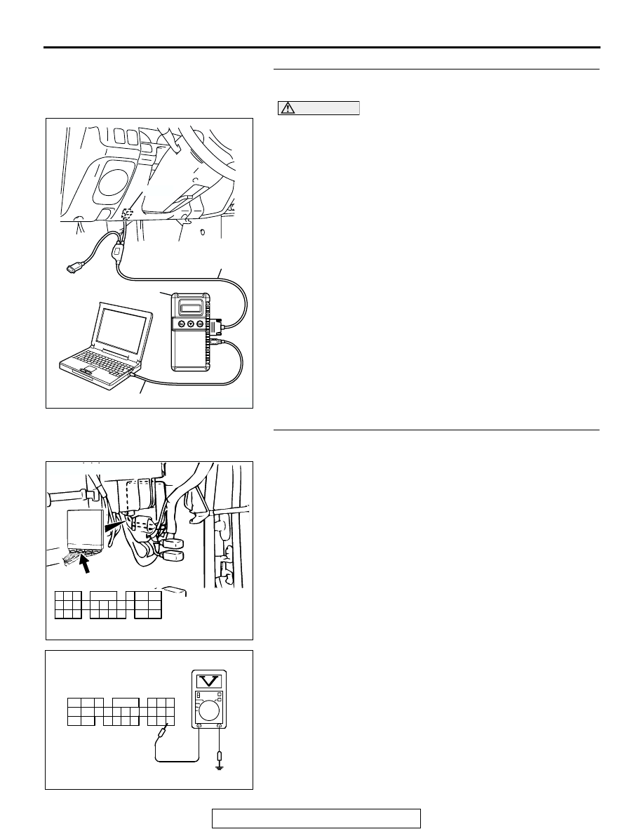
STEP 1. Using scan tool MB991958, read the diagnostic 
trouble code (DTC).

CAUTION

To prevent damage to scan tool MB991958, always turn the 
ignition switch to the "LOCK" (OFF) position before con-
necting or disconnecting scan tool MB991958.
(1) Connect scan tool MB99958 to the data link connector.
(2) Turn the ignition switch to the "ON" position.
(3) Erase the DTC.
(4) Start the engine and run it at idle.
(5) Read the DTC.
(6) Turn the ignition switch to the "LOCK" (OFF) position.
Q: Is DTC P1603 set?

YES : Go to Step 2.
NO :  The procedure is complete.

STEP 2. Measure the backup power supply voltage at PCM 
connector C-90 by backprobing.
(1) Do not disconnect the PCM connector C-90.

(2) Measure the voltage between terminal No. 66 and ground 

by backprobing.

• Voltage should be battery positive voltage.

Q: Is battery positive voltage (approximately 12 volts) 

present?
YES : 
Go to Step 5.
NO :  Go to Step 3.

AK303629AB

MB991911

MB991827

MB991824 

16-PIN

AK103762

42

43

48

49

50

51

52

53

54

55

56

57

46 45 44

58

59

60

61

62

63

64

65

66

47

41

AB

CONNECTOR: C-90

C-90(GR)

HARNESS CONNECTOR:
COMPONENT SIDE

AK000731

C-90 HARNESS 
CONNECTOR: 
HARNESS SIDE

46
57
66

45
56
65

44
55

43
49

54

64

42
48
59

41
47
58

53
63

52
62

51
61

50
60

AQ

MULTIPORT FUEL INJECTION (MFI) DIAGNOSIS

TSB Revision

MULTIPORT FUEL INJECTION (MFI)

13A-682

STEP 3. Measure the backup power supply voltage at PCM 
harness side connector C-90.
(1) Disconnect the PCM connector C-90 and measure at the 

harness side.

(2) Measure the voltage between terminal No. 66 and ground.

• Voltage should be battery positive voltage.

Q: Is battery positive voltage (approximately 12 volts) 

present?
YES : 
Go to Step 4.
NO :  Repair harness wire between battery and PCM 

connector C-90 (terminal No. 66) because of open 
circuit or short circuit to ground. Then go to Step 6.

STEP 4. Check connector C-90 at PCM for damage.
Q: Is the harness connector in good condition?

YES : Repair harness wire between battery and PCM 

connector C-90 (terminal No. 66) because of harness 
damage. Then go to Step 6.

NO :  Repair or replace it. Refer to GROUP 00E, Harness 

Connector Inspection 

P.00E-2

. Then go to Step 6.

AK103762

42

43

48

49

50

51

52

53

54

55

56

57

46 45 44

58

59

60

61

62

63

64

65

66

47

41

AB

CONNECTOR: C-90

C-90(GR)

HARNESS CONNECTOR:
COMPONENT SIDE

AKX01436

41

42

43

47

48

49

58

59

50

51

60

61

52
62

53

54

63

64

55

56

57

44

45

46

65

66

C-90 HARNESS 
CONNECTOR: 
COMPONENT SIDE

BA

AK103762

42

43

48

49

50

51

52

53

54

55

56

57

46 45 44

58

59

60

61

62

63

64

65

66

47

41

AB

CONNECTOR: C-90

C-90(GR)

HARNESS CONNECTOR:
COMPONENT SIDE

MULTIPORT FUEL INJECTION (MFI) DIAGNOSIS

TSB Revision

MULTIPORT FUEL INJECTION (MFI)

13A-683

STEP 5. Check connector C-90 at PCM for damage.
Q: Is the harness connector in good condition?

YES : Replace the PCM. Then go to Step 6.
NO :  Repair or replace it. Refer to GROUP 00E, Harness 

Connector Inspection 

P.00E-2

. Then go to Step 6.

STEP 6. Using scan tool MB991958, read the diagnostic 
trouble code (DTC).

CAUTION

To prevent damage to scan tool MB991958, always turn the 
ignition switch to the "LOCK" (OFF) position before con-
necting or disconnecting scan tool MB991958.
(1) Connect scan tool MB991958 to the data link connector.
(2) Turn the ignition switch to the "ON" position.
(3) Read the DTC.
(4) Turn the ignition switch to the "LOCK" (OFF) position.
Q: Is DTC P1603 set?

YES : Repeat the troubleshooting.
NO :  The procedure is complete.

AK103762

42

43

48

49

50

51

52

53

54

55

56

57

46 45 44

58

59

60

61

62

63

64

65

66

47

41

AB

CONNECTOR: C-90

C-90(GR)

HARNESS CONNECTOR:
COMPONENT SIDE

AK303629AB

MB991911

MB991827

MB991824 

16-PIN

MULTIPORT FUEL INJECTION (MFI) DIAGNOSIS

TSB Revision

MULTIPORT FUEL INJECTION (MFI)

13A-684

DTC P2227: Barometric Pressure Circuit Range/Performance Problem

GREEN-

YELL

OW

AK302268

Barometric Pressure Sensor Circuit

PINK

BL

ACK

BL

ACK

5V

POWERTRAIN CONTROL MODULE (PCM)

46

1

55

57

15

2

5

12

BAROMETRIC PRESSURE SENSOR
(INCORPORATED IN VOLUME
AIRFLOW SENSOR)

1 2 3 4 5 6 7

A-01

1

10

2 3 4 5 6 7 8 9

11

12 13 14 15 16 17 18 19 20 21 22

23 24 25 26 27 28 29 30 31 32 33

C-71

JOINT
CONNEC-
TOR (4)

47

41

42 43

48 49 50 51 52 53 54 55 56 57

46

45

44

58

59

60 61 62 63

64 65 66

C-90
(MU803781)

AK103908

CONNECTOR: A-01

BAROMETRIC
PRESSURE
SENSOR

A-01(B)

AC

AK103738AC

CONNECTOR: C-90

PCM

C-90(GR)


Content   ..  315  316  317  318   ..