Mitsubishi Montero Sport (2004+). Manual - part 313


  Index      Mitsubishi     Mitsubishi Montero Sport - service repair manual 2004 year


Search            


Content   ..  311  312  313  314   ..


Mitsubishi Montero Sport (2004+). Manual - part 313


MULTIPORT FUEL INJECTION (MFI) DIAGNOSIS

TSB Revision

MULTIPORT FUEL INJECTION (MFI)

13A-665

.

TROUBLESHOOTING HINTS (The most likely 
causes for this code to be set are:)

• Power steering pressure switch failed.

• Open or shorted power steering pressure switch 

circuit, harness damage or connector damage.

• PCM failed.

DIAGNOSIS

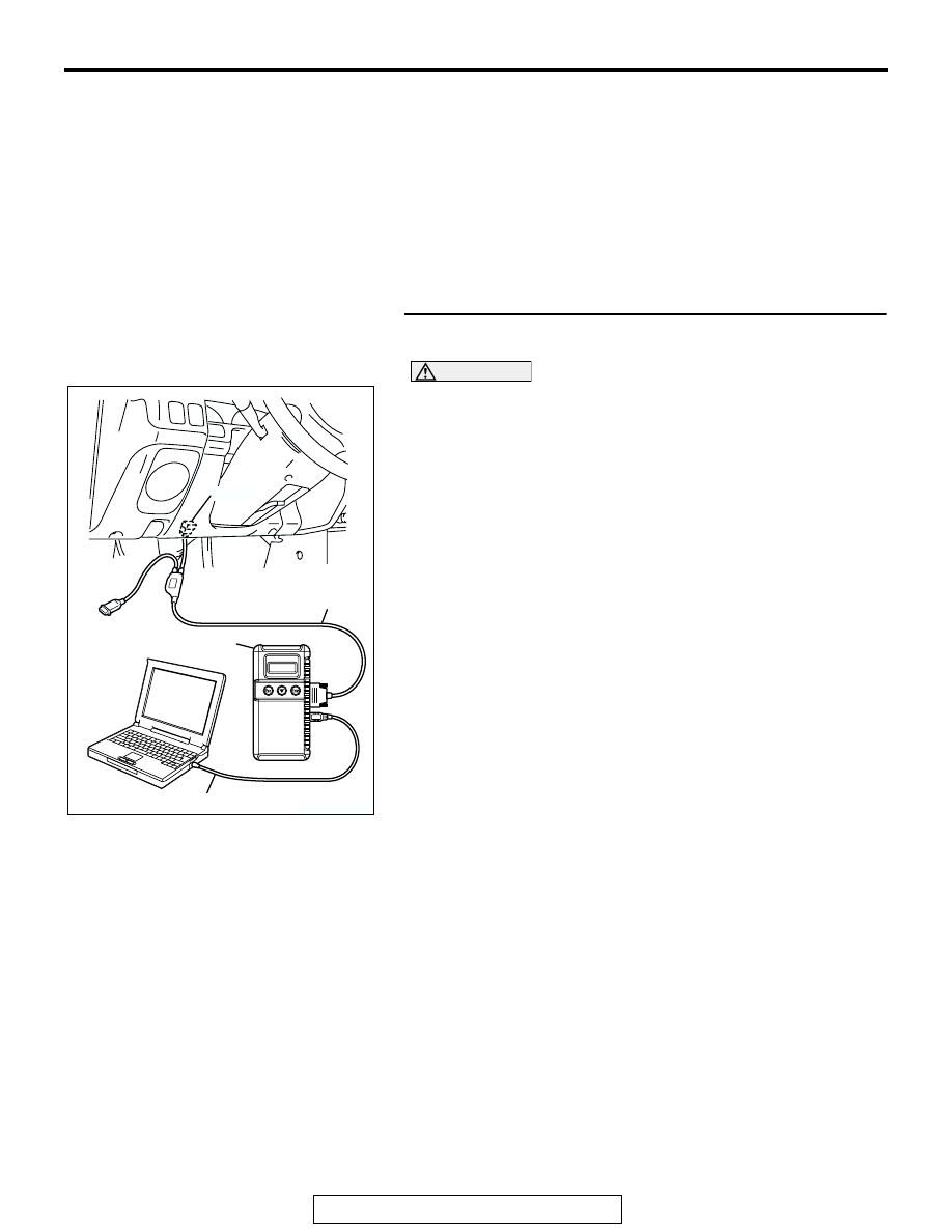
Required Special Tools:

• MB991958: Scan Tool (MUT-III Sub Assembly)

• MB991824: V.C.I

• MB991827: USB Cable

• MB991911: Main Harness B

STEP 1. Using scan tool MB991958, check data list item 27: 
Power Steering Pressure Switch.

CAUTION

To prevent damage to scan tool MB991958, always turn the 
ignition switch to the "LOCK" (OFF) position before con-
necting or disconnecting scan tool MB991958.
(1) Connect scan tool MB991958 to the data link connector.
(2) Start the engine and run at idle.
(3) Set scan tool MB991958 to the data reading mode for item 

27, Power Steering Pressure Switch.

• If the steering wheel is stopped while idling, "OFF" will 

be displayed.

• If the steering wheel is steered while idling, "ON" will be 

displayed.

(4) Turn the ignition switch to the "LOCK" (OFF) position.
Q: Is the sensor operating properly?

YES : It can be assumed that this malfunction is intermittent. 

Refer to GROUP 00, How to Use 
Troubleshooting/Inspection Service Points 

P.00-7

.

NO :  Go to Step 2.

AK303629AB

MB991911

MB991827

MB991824 

16-PIN

MULTIPORT FUEL INJECTION (MFI) DIAGNOSIS

TSB Revision

MULTIPORT FUEL INJECTION (MFI)

13A-666

STEP 2. Measure the power supply voltage at power 
steering pressure switch connector A-76 by backprobing.
(1) Do not disconnect the connector A-76.
(2) Start the engine and run at idle.

(3) Measure the voltage between terminal No.1 and ground by 

backprobing.

• When steering wheel is stationary, voltage should mea-

sure battery positive voltage.

• When steering wheel is turned, voltage should measure 

1 volt or less.

(4) Turn the ignition switch to the "LOCK" (OFF) position.
Q: Is the measured voltage within the specified range?

YES : Go to Step 3.
NO :  Go to Step 5.

STEP 3. Check connector A-76 at power steering pressure 
switch for damage.
Q: Is the connector in good condition?

YES : Go to Step 4.
NO :  Repair or replace it. Refer to GROUP 00E, Harness 

Connector Inspection 

P.00E-2

. Then go to Step 14.

AK200031

1

AB

CONNECTOR: A-76

A-76

HARNESS CONNECTOR:
COMPONENT SIDE

AK000259AI

1

A-76 HARNESS 
CONNECTOR: 
HARNESS SIDE

AK200031

1

AB

CONNECTOR: A-76

A-76

HARNESS CONNECTOR:
COMPONENT SIDE

MULTIPORT FUEL INJECTION (MFI) DIAGNOSIS

TSB Revision

MULTIPORT FUEL INJECTION (MFI)

13A-667

STEP 4. Using scan tool MB991958, check data list item 27: 
Power Steering Pressure Switch.

CAUTION

To prevent damage to scan tool MB991958, always turn the 
ignition switch to the "LOCK" (OFF) position before con-
necting or disconnecting scan tool MB991958.
(1) Connect scan tool MB991958 to the data link connector.
(2) Start the engine and run at idle.
(3) Set scan tool MB991958 to the data reading mode for item 

27, Power Steering Pressure Switch.

• If the steering wheel is stopped while idling, "OFF" will 

be displayed.

• If the steering wheel is steered while idling, "ON" will be 

displayed.

(4) Turn the ignition switch to the "LOCK" (OFF) position.
Q: Is the sensor operating properly?

YES : It can be assumed that this malfunction is intermittent. 

Refer to GROUP 00, How to Use 
Troubleshooting/Inspection Service Points 

P.00-7

.

NO :  Replace the PCM. Then go to Step 14.

STEP 5. Check connector A-76 at power steering pressure 
switch for damage.
Q: Is the connector in good condition?

YES : Go to Step 6.
NO :  Repair or replace it. Refer to GROUP 00E, Harness 

Connector Inspection 

P.00E-2

. Then go to Step 14.

AK303629AB

MB991911

MB991827

MB991824 

16-PIN

AK200031

1

AB

CONNECTOR: A-76

A-76

HARNESS CONNECTOR:
COMPONENT SIDE

MULTIPORT FUEL INJECTION (MFI) DIAGNOSIS

TSB Revision

MULTIPORT FUEL INJECTION (MFI)

13A-668

STEP 6. Measure the power supply voltage at power 
steering pressure switch harness side connector A-76.
(1) Disconnect the connector A-76 and measure at the harness 

side.

(2) Turn the ignition switch to the "ON" position.

(3) Measure the voltage between terminal No. 1 and ground.

• Voltage should be battery positive voltage.

(4) Turn the ignition switch to the "LOCK" (OFF) position.
Q: Is battery positive voltage (approximately 12 volts) 

present?
YES : 
Go to Step 11.
NO :  Go to Step 7.

STEP 7. Measure the power supply voltage at PCM 
connector C-90 by backprobing.
(1) Do not disconnect the PCM connector C-90.
(2) Disconnect the power steering pressure switch connector 

A-76.

(3) Turn the ignition switch to the "ON" position.

(4) Measure the voltage between terminal No. 52 and ground 

by backprobing.

• Voltage should be between battery positive voltage.

(5) Turn the ignition switch to the "LOCK" (OFF) position.
Q: Is battery positive voltage (approximately 12 volts) 

present?
YES : 
Go to Step 8.
NO :  Go to Step 9.

AK200031

1

AB

CONNECTOR: A-76

A-76

HARNESS CONNECTOR:
COMPONENT SIDE

AK000260AK

1

A-76 HARNESS 
CONNECTOR: 
COMPONENT SIDE

AK103762

42

43

48

49

50

51

52

53

54

55

56

57

46 45 44

58

59

60

61

62

63

64

65

66

47

41

AB

CONNECTOR: C-90

C-90(GR)

HARNESS CONNECTOR:
COMPONENT SIDE

AKX01552

41

AG

C-90 HARNESS CONNECTOR: 
HARNESS SIDE

42 43

44 45 46

47 48 49 50 51 52 53 54 55 56 57

58 59

60 61

63

64

66

65


Content   ..  311  312  313  314   ..