Mitsubishi Montero Sport (2004+). Manual - part 309


  Index      Mitsubishi     Mitsubishi Montero Sport - service repair manual 2004 year


Search            


Content   ..  307  308  309  310   ..


Mitsubishi Montero Sport (2004+). Manual - part 309


MULTIPORT FUEL INJECTION (MFI) DIAGNOSIS

TSB Revision

MULTIPORT FUEL INJECTION (MFI)

13A-649

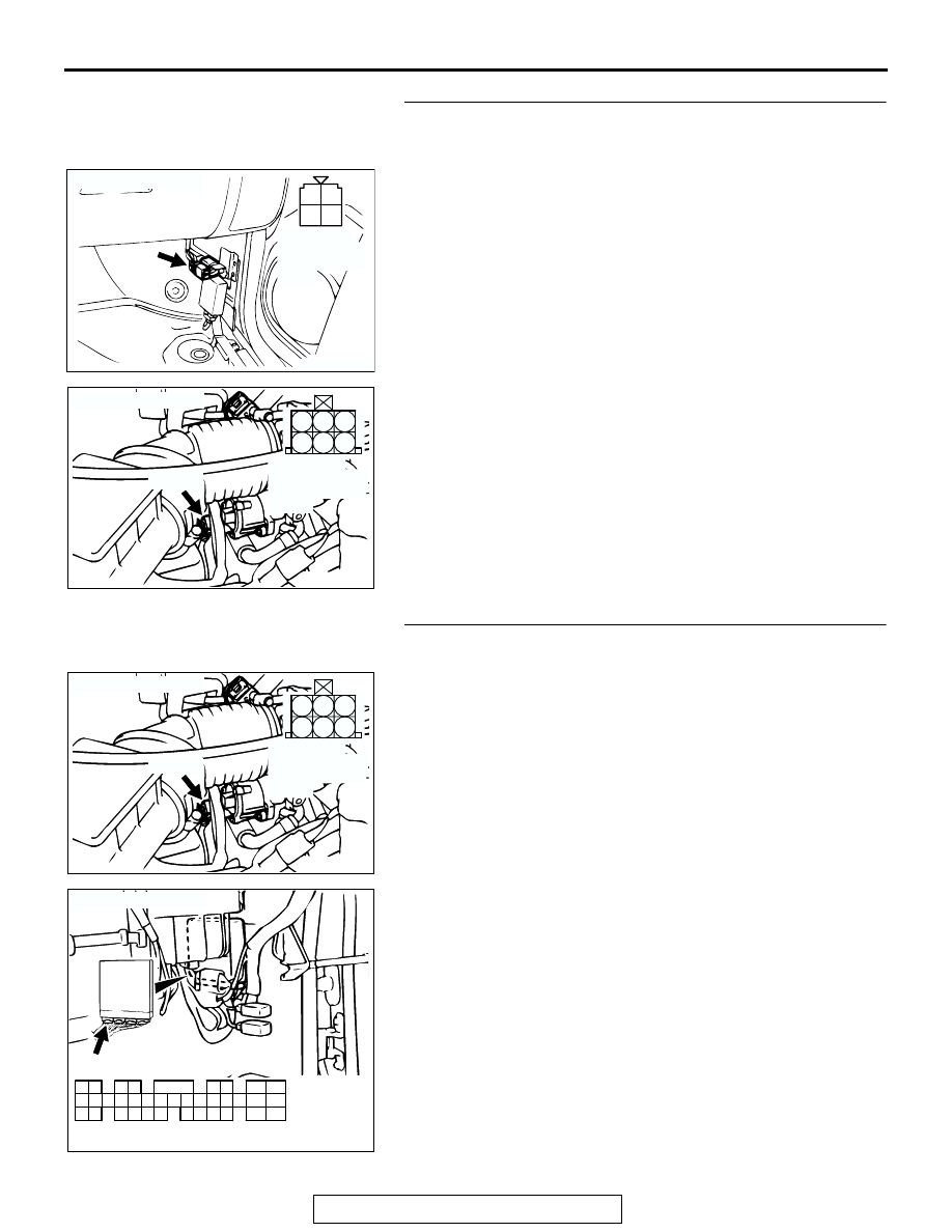
STEP 12. Check for harness damage between MFI relay 
connector C-59 (terminal No. 1) and idle air control motor 
connector A-40 (terminals No. 2, No. 5).
Q: Is the harness wire in good condition?

YES : Go to Step 13.
NO :  Repair it. Then go to Step 14.

STEP 13. Check for harness damage between idle air 
control motor connector A-40 and PCM connector C-89.

a. Idle air control motor connector A-40 (terminal No. 1) and 

PCM connector C-89 (terminal No. 14).

b. Idle air control motor connector A-40 (terminal No. 3) and 

PCM connector C-89 (terminal No. 28).

c. Idle air control motor connector A-40 (terminal No. 4) and 

PCM connector C-89 (terminal No. 15).

d. Idle air control motor connector A-40 (terminal No. 6) and 

PCM connector C-89 (terminal No. 29).

Q: Is the harness wire in good condition?

YES : Replace the PCM. Then go to Step 14.
NO :  Repair it. Then go to Step 14.

AK200023

2 1

3

4

CONNECTOR: C-59

AB

C-59

HARNESS 
CONNECTOR:
COMPONENT 
SIDE

AK200476

1

2

3

4

5

6

AB

CONNECTOR: A-40

A-40(B)

HARNESS 
CONNECTOR: 
COMPONENT 
SIDE

AK200476

1

2

3

4

5

6

AB

CONNECTOR: A-40

A-40(B)

HARNESS 
CONNECTOR: 
COMPONENT 
SIDE

AK103914

2

3

4

5

6

7

8

9

11

12

13

14

15

16

17

18

19

20

30

21

22

23

24

25

26

27

28

29

31

32

33

34

35

1

10

AB

CONNECTOR: C-89

C-89(GR)

HARNESS CONNECTOR:
COMPONENT SIDE

MULTIPORT FUEL INJECTION (MFI) DIAGNOSIS

TSB Revision

MULTIPORT FUEL INJECTION (MFI)

13A-650

STEP 14. Test the OBD-II drive cycle.
(1) Carry out a test drive with the drive cycle pattern. Refer to 

Diagnostic Function 

− OBD-II Drive Cycle − Procedure 6 − 

Other Monitor 

P.13A-4

.

(2) Check the diagnostic trouble code (DTC).
Q: Is DTC P0506 set?

YES : Repeat the troubleshooting.
NO :  The procedure is complete.

MULTIPORT FUEL INJECTION (MFI) DIAGNOSIS

TSB Revision

MULTIPORT FUEL INJECTION (MFI)

13A-651

DTC P0507: Idle Control System RPM Higher than Expected

WHITE-

BLA

CK

WHITE-

BLA

CK

WHITE-

BLA

CK

RED

RED

RED

GREEN-BLA

CK

GREEN-BLUE

GREEN

GREEN-RED

AK200194

Idle Air Control (IAC) Motor Circuit

2

3

4

FUSIBLE LINK (12)

1

12

2

5

17

18

6

4

3

1

MFI
RELAY

14

28

15

29

IDLE AIR
CONTROL
(IAC) MOTOR

POWERTRAIN CONTROL MODULE (PCM)

C-59

1

10

2 3 4 5 6 7 8 9

11

12 13 14 15 16 17 18 19 20 21 22

23 24 25 26 27 28 29 30 31 32 33

C-14

10

2

3 4

5 6

7 8

9

11 12 13 14 15 16 17 18 19 20

30

21 22 23

24

25

26 27 28 29

31 32 33

34 35

1

C-89
(MU803784)

2

4 5 6

3

1

A-40

JOINT
CONNECTOR (5)

1

2

3

4

MULTIPORT FUEL INJECTION (MFI) DIAGNOSIS

TSB Revision

MULTIPORT FUEL INJECTION (MFI)

13A-652

.

CIRCUIT OPERATION

• The idle air control (IAC) motor power is supplied 

from the MFI relay (terminal No. 1).

• The PCM (terminals No. 14, No. 15, No. 28, No. 

29) drives the stepper motor by sequentially turn-
ing "ON" the power transistors in the PCM and 
providing ground to the idle air control motor (ter-
minals No. 1, No. 3, No. 4, No. 6).

.

TECHNICAL DESCRIPTION

• The amount of air taken in during idling is regu-

lated by the opening and closing of the servo 
valve located in the air passage that bypasses 
the throttle body.

• If there is a malfunction of the IAC system, the 

actual engine speed will not be identical to the 
target engine speed.

• The PCM checks the difference between the 

actual engine speed and the target engine speed.

.

DESCRIPTIONS OF MONITOR METHODS
Difference between actual and target idle speed is 

over the specified value.

.

MONITOR EXECUTION
Continuous

.

MONITOR EXECUTION CONDITIONS (Other 
monitor and Sensor)

Other Monitor (There is no temporary DTC stored 

in memory for the item monitored below)

• Misfire monitor

• Exhaust gas recirculation (EGR) system monitor

• Fuel system monitor

Sensor (The sensor below is determined to be 

normal)

• Volume airflow sensor

• Engine coolant temperature sensor

• Intake air temperature sensor

• Barometric pressure sensor

• Throttle position sensor

.

AK200029 AB

CONNECTOR: A-40

IDLE AIR CONTROL MOTOR

A-40(B)

AK201000

MFI RELAY

CONNECTOR: C-59

AB

C-59

AK103911AB

CONNECTOR: C-14

C-14

AK103738AD

CONNECTOR: C-89

PCM

C-89(GR)


Content   ..  307  308  309  310   ..